Mobile Robot For Hobbyist, Research and Education Assembly and User Guide Copyright (c) 2005 Arrick Robotics All Rights Reserved Robotics.
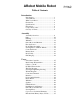
ARobot Mobile Robot Table of Contents Introduction Introduction....................................................1 About ARobot................................................1 What You’ll Need ..........................................2 Feature List ....................................................2 Specifications.................................................3 Precautions.....................................................4 Component Locator .......................................
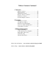
Table of Contents Continued Connectors Battery Connector ..........................................36 Body Connector .............................................36 Serial Port Connector.....................................36 RC Servo Motor Connectors..........................37 DC Motor Connector .....................................37 Powerful Output Connector ...........................37 Expansion Expansion Connector .....................................38 User RC Servo Motors........................
Introduction Congratulations for purchasing the ARobot mobile robot. This manual should answer all of your questions. We suggest that you read and understand all of it before using your new robot. If you have any questions, please view our web site at www.robotics.com/arobot The software provided is designed for use with IBM-style personal computers. This manual assumes the user has full understanding of how to use their computer and operating system.
What You’ll Need To build and program ARobot you will need the following items: Common hand tools – screwdriver, pliers, etc. Your choice of spray paint (optional). Basic Stamp II computer chip. Basic Stamp II programming information – available free on the Internet or you can purchase a book. Understanding of Basic programming or a willingness to learn. IBM style PC running DOS or Windows, 3-1/2“ disk drive, unused serial port (9 pin connector). Internet access for technical support and application notes.
Technical Specifications Body: .062 aluminum - cut, punched, and formed. Configuration: 3-wheel, front wheel drive, rear wheel steer. Dimensions: 10" x 10", 5" tall, 2-1/4 lbs. Payload capacity: 1 lbs. Wheel size: 3.25" diameter. Drive Motor: 12 volt DC gear motor, 74 full load RPM, 1.6 amp full load current. Quality machined wheel coupling and bearings. Optical wheel encoder for distance measurement Encoder: 20 counts per revolution - 2 per inch of travel (1/2” resolution).
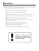
Precautions The following precautions must be taken to insure trouble free operation of ARobot. The order that these precautions are listed does not indicate their importance. Failure to observe these precautions may result in loss of life, damage of property and/or damage to the Robot. Never attach or remove cables while power is applied to the Robot. Never use the robot in areas near water such as swimming pools.
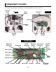
Component Locator Use the following diagrams to familiarize yourself with ARobot' s various components.
Glossary of Terms Analog Signals – Signals that have values between on and off (1 and 0). Android – A robot that has a human-like form. Artificial Intelligence (AI) – A computer program that simulates intelligence like that found in biological systems. Artificial Life – Behavior that is simulated by a computer program or other machine that mimics some or all aspects of biological life. Baud Rate – The number of bits per second.
Glossary of Terms continued Fractals – A geometric pattern in which an object looks the same regardless of the viewing scale. Fractal concepts can be used in AI programming. Fuzzy Logic – Logic in which boundaries between sets are not crisp. This concept is often used to control systems that would be too complex to model with traditional sequential programs. Genetic Algorithm – A set of instructions that mimic biological life by simulating genes, mutation, and other aspects of living systems.
Glossary of Terms continued Mechatronics – A combination of mechanical and electrical devices to create a system. Natural Language – Language used by humans to communication. Neural Network – A network of processing elements that are connected together to simulate the intelligence created by biological brains. Often used to perform pattern recognition. Open Loop – in motor control, the lack of a feedback device. Parallel Data – Data that is transmitted multiple bits at a time using multiple wires.
Assembly Overview ARobot’s assembly normally takes about 2 hours or less excluding time for painting. Children as young as 10 can build ARobot with the help of an adult. The controller board and cables are pre-built, so soldering is not required. During assembly you will do these things: Sand and paint the metal robot body pieces (this is optional). Mounting whiskers, drive motor, steering motor, wheels, etc. Route cables. Install the Basic Stamp II onto the controller board.
Parts ARobot is easy to put together. Make sure you have all of the parts listed below before beginning. If something doesn’t look right, send us some email at info@robotics.
Parts continued Here are drawings of SOME of the parts in the ARobot package. Drawings are not to scale. As you build ARobot, refer back to these drawings to identify parts.
Parts continued Encoder Wheel Motor Brackets RC Servo Steering Motor Drive Motor Body Cable Controller Battery Cable Body Encoder Sensors Wire Ties Battery Holder 4-40 x 3/8 4-40 x 3/16 Front Axle Whisker Wires Whisker Shoulder Washers Steering Linkages Whisker Spacers Bronze Bearing Whisker Plastic Washers Rear Axles Velcro Steering Arms Controller Spacers 4-40 nuts Collars 10-32 nuts 12 #4 Star Washers 6-32 x 1/4
Painting ARobot' s paint job is your first chance to be creative and have a little fun. Who wants every robot to look alike anyway? Five parts are candidates for painting: The robot base, 2 motor brackets, encoder wheel, and the motor coupling. Or if you prefer, simply leave these parts unpainted. Here' s the process: Sanding Paint primer Finish coat Accents Sanding Sand the metal, especially the edges, with fine sand paper (200-600 grit). This process could also be done with a file.
Whiskers Two whisker wires are mounted on the front of the robot to detect obstacles. Locate the 4 whisker mounting holes near the front center of the robot body. Scratch off paint around the two smaller holes. Next, bend each whisker wire using the drawing as a full scale pattern. Locate the body cable and find the ground lug. Mount the 2 whisker spacers like the drawing and place the ground wire from the body cable under one of the whisker spacers and a #4 star washer under the other.
Whiskers continued Whisker Detail Full Scale Whisker Wire Pattern 3” 1-1/2” 8-3/4” Total Length 4” Bend both whisker wires using this pattern 15 Small Loop Attaches to Whisker Spacer
Drive Motor and Brackets Locate the two motor brackets – a left side and a right side. Locate the drive motor. Mount the drive motor to the left motor bracket using 2 or 3 screws according to the drawing. Next, attach the motor brackets to the robot’s body using 3 screws, 3 star washers, and 3 nuts per motor bracket. Minor bending may be required to align the mounting holes. Summary: Locate the 2 motor brackets (left and right sides), and the drive motor.
Encoder Sensor The encoder sensor counts the teeth in the encoder wheel using invisible IR (infrared) light to measure the distance traveled. The encoder wheel has teeth that interrupt the beam of light. Locate the encoder sensor and notice the dots placed on it (see the drawing). Mount the sensor using 2 screws, 2 star washers, and 2 nuts. The encoder wheel will be mounted to the axle later. Summary: Locate the encoder sensor. Mount the encoder sensor on the right wheel bracket according to the drawing.
Front Wheel Assembly A picture is worth a thousand words – so take a look at the drawings below before starting to building the front wheel assembly. First locate the front wheel which has a threaded bore and a red mark on the hub. Screw the threaded front axle into the wheel so that one side of the axle protrudes about 1/2 inch from the wheel’s hub. Follow the assembly summary below while looking at the drawings. If you bend the whisker wires in this process don’t worry, we’ll fix them later.
Steering Motor and Rear Wheels Steering of the robot is accomplished using a standard RC servo motor attached to the rear wheels. Read the assembly summary while viewing the drawings. Summary: Bend both 4” wires into steering linkages with pliers using the drawing as a pattern. Attach the horn to the steering motor with a screw. Turn the horn in both directions to determine the center position. In the center position, the horn should be oriented like the drawing shows.
Steering Motor and Rear Wheels Steering Motor Mounting Wheel and Axle Steering System 20 continued
Controller Board ARobot’s controller board is the brains of the system. It accepts a Basic Stamp II controller chip which can be programmed from a personal computer. The controller board contains electronics used to drive the motors, sound the speaker, control the LEDs, read whiskers, etc. An expansion port allows additional circuits to be added to the system. The controller board is mounted to the robot body using 4) 1” plastic spacers and 4) 6-32 x 1/4 screws.
Battery Pack Don’t install batteries yet. Power is supplied to ARobot using a battery pack that contains 8 AA size batteries. Locate the battery cable which has a batter snap on one end and a 2-pin MTA connector on the other. Pin 1 has the red wire and is +12 volts, Pin 2 is the black wire and is ground (0 volts). Plug the MTA connector from the battery cable onto the power connector on the controller board. Route the other end through a nearby hole in the robot body.
Body Cable The body cable connects the controller to the encoder sensor, whiskers, and ground lug. The body cable will already be attached to the robot because we have already installed the whiskers and ground lug. Route the body cable up through the rectangular hole in the robot’s body. Plug the body cable into the controller’s 10 pin body connector which is next to the expansion connector. It will only install one way. Next find the 2 MTA connectors on the body cable.
Finishing Up You’re almost finished building ARobot. Finish up by doing these things: Route the steering motor cable up though the rectangular hole in the robot body. Connect the steering motor cable to the 3 pin connector on the controller board near the body connector (see the controller drawing). Align the white (sometimes yellow) wire to pin 1. Installing this cable backwards will not harm the motor or controller, but it will not work.
About the Controller Board The Controller board is the brains of ARobot. It contains circuitry to control the steering and drive motors, read the whiskers, control LEDs, speaker, buttons, etc. The controller board has a socket that accepts a Basic Stamp II control computer chip designed by Parallax Inc. www.parallaxinc.com The Basic Stamp II is programmed with a desktop PC through the serial port in the PBasic Language which is much like standard Basic but with some interesting additions.
Cable to your PC ARobot’s controller board is programmed by connecting it to an Personal Computer (PC) running Microsoft Windows. The serial port (9 pin male connector) will be used for this. A 9 pin male-female cable is included to connect your PC’s serial port to ARobot. It may be necessary to remove your modem or other device (except your mouse) to free up the serial port. Switch boxes are also available from computer stores that allow one serial port to serve two devices.
Programs The ARobot package includes programs to: Test Program to test motors, buttons, whiskers, speaker, LEDs, etc. Steering adjustment program to set the straight position of the steering motor. Wander program will move around avoiding obstacles. Other programs and projects for ARobot are available at our website: www.robotics.com/arobot Test Program: TEST.BS2 The test program tests all functions on ARobot. When it powers up, it beeps several times to test the speaker.
About the Controller Board 28
Batteries ARobot’s controller board requires 9 to 12 volts supplied by 8 AA size batteries. We’ve found that the best batteries are DuraCells. You can also use AA size rechargeable batteries. First turn the controller board off and remove the battery pack from the battery cable. Install the 8 batteries observing polarity + - which is indicated on the holder. Snap the cable back onto the pack and stick the pack to the body with Velcro.
Whiskers Whisker wires are used to detect objects while the robot is moving. There is a left and right whisker which can be read separately to determine the location of the object. The left whisker is connected to the P0 pin and the right whisker is connected to the P1 pin. When an object is detected, these pins return a logic zero (low). The pins must be in the input mode. The following PBasic code example shows how the whiskers can be read.
Push Buttons and Jumpers (switches) Two general purpose buttons and jumpers (also called switches) are provided on the controller card which can be read by the Basic Stamp II. Buttons are momentary – after you press them they return to the off state. Jumpers can be left in the on or off position using the jumper plug or wired to external switches. Buttons and Jumpers can be use in your program to set certain parameters or modes as needed. They may be ignored and not used at all.
Drive Motor and Encoder continued The previous subroutine will START the drive motor. You can monitor the progress of the drive wheel by reading the encoder counter from the coprocessor. Here is example code that will read the encoder. ec var word serout net,baud,["!1E1"] serin net,baud,[hex4, ec] 'Encoder count. 'Ask for encoder count. 'Get encoder count into ec. You can use this code within a loop to wait until the desired distance is completed.
Coprocessor Command Summary This section describes how the coprocessor works and how each command is constructed. The controller board contains a coprocessor that is used to control the drive motor, powerful output, encoder sensor, and the 4 RC servo motors (#1 is used as the steering motor). This frees the Basic Stamp II for other tasks. The coprocessor receives commands from the Basic Stamp II via the coprocessor network bus on pin P8.
Coprocessor Command Summary continued RC Servo Motor and Steering Motor Control: Example: !1R380 This command begins with “!1R” and is followed by a character indicating the RC servo motor number (3 in the example), followed by the position in hexadecimal (80 in the example). Possible position values are “01” through “FF” which results in about 120 degrees of motion. This varies depending on the motor. A position value of 80 hexadecimal will center the motor.
Hexadecimal, Binary, Bytes, Words, etc. Most commands require parameters in the form of hexadecimal values and many commands return hexadecimal values. Sometimes the bits in these values will represent certain things. We’ll use the term “hex” to refer to hexadecimal. Hexadecimal Hex numbers are easy for computers to work with because each hex digit can represent 4 bits, 2 hex digits can represent a byte, and 4 hex digits can represent a word. Sometimes hex digits are referred to as nibbles.
Battery Connector (J9) Usage: Supplies battery power to all systems. Type: 2 pin, MTA, .1” Pinout: 1 – +12 volts 2 – Ground Body Connector (J8) Usage: Connects controller to encoder, whiskers, and ground lug. Connector: 10 pin, dual row header, .
RC Servo Motor Connectors (J2-J5) Usage: Connects controller to RC servo motors. J2 is used for the steering motor. J3, J4, J5 are user defined. Controlled by the coprocessor Connector: 3 pin, .1”, 4 total Pinout: 1 – Control Pulse 2 – +5 volts 3 – Ground Drive Motor Connector (J10) Usage: Connects H-Bridge driver to DC motors. Controlled by coprocessor. Polarity can be controlled. Type: 2 pin, MTA, .
Expansion Connector (J1) Usage: Connects controller to user devices. Connector: 40 pin .1 IDC Header Pinout: 1 – Ground 2 – Ground 3 – +5 volts, 200ma max 4 – +5 volts, 200ma max 5 – P0 of Basic Stamp II, Left whisker 6 – P1 of Basic Stamp II, Right whisker 7 – P2 of Basic Stamp II, to body conn.
Expansion Port Circuit Examples ARobot' s expansion connector provides access to the Basic Stamp II’s I/O pins, to the RC servo motor signals, and to the wheel encoder’s signal. These signals can be used to control accessories and to read sensors. +5 volts is made available to power accessories. Observe current specifications to prevent overload of the power supply components on the controller board.
Expansion Port Circuit Examples continued Digital Inputs Basic Stamp input signals can be used to read TTL level signals such as switches or sensors. The input signal should not exceed +5 volts DC or go below 0 volts. Each input pin has a pull-up resistor to +5 volts. Switch Input Example: This example shows how to interface a mechanical switch to one of the digital Sensor Input Example: This example shows how to interface a sensor that has an open collector (OC) output to a digital input.
Expansion Port Circuit Examples continued Analog Inputs Analog inputs are inputs that can vary from 0 to 5 volts. While the Basic Stamp II doesn’t have a true analog input, analog signals can be read using a little trick. This is done by adding a capacitor to ground on a digital I/O pin and a resistive sensor to +5 volts.
Coprocessor Network Expansion The complete application note for coprocessor expansion can be found on our website at: www.robotics.com/arobot/projects.html A coprocessor is one of the most powerful expansions that can be added to ARobot. A coprocessor can remove time consuming tasks from the master processor, leaving it for higher level routines. The coprocessor could be used to add a ring of sonar range finders, read a time consuming compass, process video images, control motors, etc.
Using Other Controllers ARobot’s controller board is designed to accept the Basic Stamp II controller chip made by Parallax (www.parallaxinc.com). Parallax makes other Basic Stamp II compatible controllers which offer more memory and greater speed. Other manufacturers also make controllers that are compatible with the Basic Stamp II and most of them should work fine with ARobot' s controller board. It is possible to remove the Basic Stamp II and use a different type of high-level controller board.
Suggested Reading PC AI Magazine Knowledge Technology, Inc. 3310 West Bell Rd., Suite 119 Phoenix, AZ 85023 (602) 971-1869 Periodical covering PC-based AI topics. 4 Park St. #20 Vernon, CT 06066 (203) 875-2751 Monthly periodical covering computer control projects. Embedded Systems Programming Miller Freeman Inc. 600 Harrison St. San Francisco, CA 94107 (415) 905-2200 Monthly periodical covering embedded computer programming. Robot Science & Technology Magazine Dedicated to Real Robots. 2351 Sunset Blvd.
Component Suppliers The following list of suppliers has been compiled to help in the expansion of ARobot. These vendors offer such items as single board computer, sensors and actuators. Most of the companies listed have catalogs which contain detailed part and technical information and can be obtained at little or no cost. Ampro Computers 990 Almanor Ave. Sunnyvale, CA 94086 (408) 522-2100 Manufactures a wide variety of computers and controller boards including PC/104 based systems.
SAVA Industries 70 Riverdale Rd. Riverdale, NJ 07457 (201) 835-0882 Manufactures cables and pulleys. Winfred M. Berg 499 Ocean Ave. East Rockaway, NY 11518 (516) 599-5010 The Berg catalog contains gears, bearings and large assortment of unusual belts and pulley systems. Small Parts 6891 N.E. 3rd Ave. P.O. Box 381736 Miami, FL 33238-1736 (305) 751-0856 This company stocks a broad range of precision parts such as screws, tubing, and tools. Z-World Engineering 1724 Picasso Ave.
Internet Robot Resources The Internet contains a wide variety of resource pertaining to robots. Virtually all Universities provide research documents and files on the Internet for those interested. Many contain information about robot programming, navigation and control issues. This information can be obtained using a Web browser such as Netscape or via FTP (File Transfer Protocol). Various newsgroups are available that allow readers to exchange ideas and ask questions.
Internet News Groups The following newsgroups are a goldmine of information. Most newsgroups have a FAQ (frequently asked questions) file associated with them that will answer many questions about the particular subject. Questions not answered in the FAQ can be posted to the newsgroup for a direct response from other readers. Parallax also offers a Basic Stamp forum – see www.parallaxinc.com Newsgroup Name Description comp.robotics.misc All aspects of robots and their applications. comp.ai comp.ai.
Troubleshooting The following list describes the most common problems and their remedies. Check our FAQ (Frequently Asked Questions) at www.robotics.com/arobot/faq.html Problem: Remedy: Turning the power switch ON does not result in any activity. ARobot is not getting power. Insure that the batteries are good and installed correctly. Insure that the batteries are touching the contacts on the battery holder. Insure that the power connector is plugged into the controller card correctly.
Warranty Information ARRICK ROBOTICS warrantees this product to be in good working order for a period of one (1) year from the date of purchase. Should this product fail to be in good working order at any time during this period, ARRICK ROBOTICS will, at its option, repair or replace the product at no additional charge except as set forth below. This limited warranty does not include service to repair damage to the product resulting from accident, disaster, misuse, abuse, or modification of the product.
Robotics.