
Specifications


1
2
ON
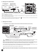
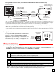
Back View of the E-35
Yellow (Video)
- Black (GND)
+ Red (6VDC)
** Camera Pwr (+) Orange
** Camera GND (-) W/O
Video GND (-) Green
Video Out (+) W/G
* Up to 150 ft
3-Wire Gel-Filled Butt
Connectors included
(3M Scotchlok UR2)
CAT5E or
CAT6 Cable
(see Caution below)
Phono (RCA) Plug,
F Connector, Etc.
(+)
(-)
To unused input on TV, VHF
modulator, whole house video
distribution equipment, IP video
encoder (Axis M7001), etc.
Video Out (+)
Video GND (-)
See page 4, section E
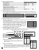
Wiring Phone Board
Blue W/BL
W/G Green
W/O
Orange
120V AC
Camera GND (-)
Camera Power (+)
Black with
White Stripe
5V DC Adapter
(included)
Black
(-)
!
(+)
(4) Crimp-on Splice
Connectors (not included)
Phone Board Audio In/Out (Tip) W/BL
Phone Board Audio In/Out (Ring) Blue
* Note: Up to 150 ft video cable run length can be achieved using CAT5E or CAT6 cable. Longer cable runs can be used if a passive or active video Balun transceiver is used on
each end of the cable. Generally, passive transceivers can achieve up to 750 ft cable runs where active transceivers can achieve up to 3000 ft runs depending on cable type, etc.
The type of video balun transceiver required is specific to your cable run length. For more information on video balun transceivers go to: www.northernvideo.com.
Caution: When routing CAT5E or CAT6 cable, maintain a minimum distance of 3 ft from any parallel high voltage wire (110 VAC) and a minimum of 2 ft from crossing any high volt-
age wire. For installations where RF noise is expected (commercial applications) or wire runs are near high voltage (110 VAC) wires, a shielded video cable such as RG6 is recom-
mended.
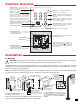
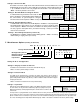
G. Adjusting the Camera
The camera can be tilted and rotated to your desired posi-
tion. A portable service (test) monitor can be used to
determine the correct viewing angle during installation.
Important: To prevent the edge of the faceplate from
being viewed in the video image, do not rotate the cam-
era beyond 30 degrees or tilt beyond 20 degrees.
Vertical (Tilt)
Adjustment
+/- 20 degrees
maximum
Horizontal (Rotation)
Adjustment
+/- 30 degrees maximum
Call
VIKING
©
** Note: The maximum camera power supply wire run length is 500 ft of 24 gauge wire (CAT 5/6), longer runs are possible by doubling pairs or increasing the wire gauge.
2. Using CAT5E or CAT6 for Video, Camera Power and Phone Board Audio (see Caution below)
*** Note: RG59 or RG6 with solid center conductor and 95% bare copper braid shield.
P
P
r
r
o
o
g
g
r
r
a
a
m
m
m
m
i
i
n
n
g
g
Step 1. Move DIP switch 2 to the ON position (sets unit to answer incoming calls - see section H).
Step 2. From a Touch Tone phone call the line attached to the E-35.
Step 3. When the E-35 answers, enter the 6-digit security code (factory set to 845464 - see section C). A double beep
should then be heard indicating you have entered the programming mode.
2. Without the Security Code
A. Accessing the Programming Mode
1. Using the Security Code
Step 1. Move DIP switch 2 to the ON position (sets unit to answer incoming calls - see section H).
Step 2. Move DIP switch 3 to OFF (incoming calls enter the programming mode without security code - see section H).
Step 3. From a Touch Tone phone call the line attached to the E-35.
Step 4. When the E-35 answers, a double beep will be heard and you will automatically enter the programming mode.
Step 5. When finished programming, move DIP switch 3 back to the ON position (see section H).
The E-35 phone can be programmed from any Touch Tone phone using a C.O. line, analog PABX/KSU station, or a
DLE-200B Line Simulator. For more information on the DLE-200B, see DOD# 605.
5
Warning: Failure to do step 5 above will cause the E-35 to call Viking Technical Support instead of your programmed number.
Note: If a valid memory position is entered, a double beep will be heard, four beeps indicate an error.