
Specifications


LED3
LED1 LED2
LED4
LED5
LED6
LED7
C
CCCC
C C
J11-
1
2
3
J10-
12
3
J9-
1
2
3
J8-
1
2
3
J7-
1
2
3
1 2 3
on
on
4 5
VIKING
©
MODEL C-2000B
VIKING
ELECTRONICS
HUDSON, WI 54016
ADVANCED DOOR/GATE AND
ENTRY PHONE CONTROLLER
1 2 3 4 5 6 7
89
10 1 1 12 13 15 16 17 18 19 20 21 22 23 24 25 26 27 28 29 30 31 32
PWR 13.8 VAC
EARTH GND
ENTRY PHONE 1
DOOR STRIKE 1
ENTRY PHONE 2
DOOR STRIKE 2
ENTRY PHONE 3
DOOR STRIKE 3
ENTRY PHONE 4
DOOR STRIKE 4
DOORBELL SWITCH /
AUX. INPUT
AUX. CONTACT
OUTPUT
PHONE LINE
INPUT
LINE OUT
TO PHONES
ANALOG STATION
INPUT
1
2
ON
5.0”
3.63”
5.0”
3.63”
or
* C.O. Line
or Analog
PABX/KSU
Station
Ring
Terminal
(included)
*** Earth
Ground
(optional)
or
SINGLE ENTRY PHONE
CONTROLLER
VIKING
©
MODEL C-200
P
W
R
1
3
.8
V
A
C
A
U
X
R
E
L
A
Y
C
O
N
T
A
C
T
S
12345 89
10
EARTH
GND
PHONE LINE
INPUT
LINE OUT
TO PHONES
67
TO ENTRY
PHONE
VIKING
ELECTRONICS
HUDSON, WI 54016
EARTH
GND
C.O. LINE
INPUT
OUT TO
PHONES
ENTRY
PHONE
N.O. COM N.C.
AUX CONTACTS
ON
1 2 3
11 12
AUX POWER
OUTPUT
AUX POWER
OUTPUT
RING COUNT
RELAY MODE
DOORBELL MODE
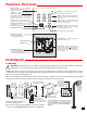
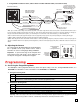
Optional C-2000B Advanced Door
Entry Controller, DOD# 156
(not included)
Optional C-200 or C-250 Basic
Single Entry Phone Interface,
DOD# 169 or 172 (not included)
Rear View of
the E-35
** Gel-Filled
Butt Connectors
Red (Ring)
Green (Tip)
*** Note: To increase surge protection, loosen the PCB mounting screw labeled (as shown above) and fasten a wire with spade terminal (included)
from the mounting screw to Earth Ground (grounding rod, water pipe, etc.)
** Note: The gel-filled (water-tight) butt connectors are designed for insulation displacement on 19-26 gauge wire with a maximum insulation of 0.082
inches. Cut off bare wire ends prior to terminating.
* Note: When installing a line powered phone on a low voltage and/or low loop current phone system extension, a TBB-1B Talk Battery Booster may be
required, see DOD# 632 for more information.
B. Wiring the E-35 Phone Board
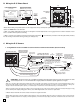
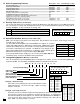
C. Wiring the E-35 Camera
1. Using RG59 for Video and CAT5 for Camera Power and Phone Board Audio (Recommended)
1
2
ON
Back View of the E-35
** Camera Pwr (+) Orange
** Camera GND (-) W/O
Yellow (Video)
3-Wire Gel-Filled Butt
Connectors included
(3M Scotchlok UR2)
CAT5 Cable
To unused input on TV,
VHF modulator, whole
house video distribution
equipment, IP video
encoder (Axis M7001), etc.
120V AC
Camera GND (-)
Camera Power (+)
Black with
White Stripe
5V DC Adapter
(included)
Black
(-)
!
(+)
Phone Board Audio In/Out (Tip) W/BL
Phone Board Audio In/Out (Ring) Blue
See page 4, section E
Wiring Phone Board
Blue W/BL
W/O
Orange
*** RG59 or RG6 Shielded
Video Cable, up to 1000 ft
Center conductor
stripped back 5/8"
Twisted foil and braided shield
** Up to 250 ft
"F"
Connector
"F" to Phono Plug
Adapter
(Radio
Shack part #278-252)
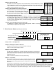
- Black (GND)
+ Red (6VDC)
Crimp-on Splice
Connectors (not included)
OR
Black
Yellow/Red
**** Female "F" to Wire or "BNC" to Wire
Converter Cable (not included)
**** For ease of installation, a Viking Female
"F" to Wire Converter Cable can be used (Part
# 261217) or "BNC" to wire converter cable
(Part # U213510) can be used. Go to
www.vikingelectronics.com and click on
"Spare Parts" to order.
IMPORTANT: Electronic devices are susceptible to lightning and power station electrical surges from both the AC outlet
and the telephone line. It is recommended that a surge protector be installed to protect against such surges.
!
4
* Note: Up to 150 ft video cable run length can be achieved using CAT5E or CAT6 cable. Longer cable runs can be used if a passive or active video Balun transceiver is used on
each end of the cable. Generally, passive transceivers can achieve up to 750 ft cable runs where active transceivers can achieve up to 3000 ft runs depending on cable type, etc.
The type of video balun transceiver required is specific to your cable run length. For more information on video balun transceivers go to: www.northernvideo.com.
Caution: When routing CAT5E or CAT6 cable, maintain a minimum distance of 3 ft from any parallel high voltage wire (110 VAC) and a minimum of 2 ft from crossing any high volt-
age wire. For installations where RF noise is expected (commercial applications) or wire runs are near high voltage (110 VAC) wires, a shielded video cable such as RG6 is recom-
mended.
** Note: The maximum camera power supply wire run length is 250 ft of 24 gauge wire (CAT 5/6), longer runs are possible by doubling pairs, increasing the wire gauge or using
a 6V DC 200mA power adapter (Viking part # L122110). Go to www.vikingelectronics.com and click on “Spare Parts”.
*** Note: RG59 or RG6 with solid center conductor and 95% bare copper braid shield.