
Owner`s manual
8
5. Cut the loop at the end of the
blue wire, strip about
1
/
2
-inch of
insulation from the end, and
connect it to any optional com-
ponents, designed to run from a
switched source, that you want
to turn on and off when you turn
the stereo on and off (such as an
equalizer/booster or a power
antenna).
This wire does not provide power
to the components. It simply turns
them on or off. If you do not use
this wire, secure it with a wire tie
and do not let it touch metal.
Testing the Power
Connections
Temporarily connect:
• The 14-pin connector into the
stereo’s 14-pin wiring socket
• Your vehicle battery’s negative
(
–
) cable
Then turn on your vehicle’s ignition.
Verify that everything works properly
(the stereo works properly when the
display lights and the time display ap-
pears after about 5 seconds).
Caution:
If the display lights but the
time display does not appear, the
power and ground connections might
be reversed.
If the stereo does not work,
immedi-
ately turn off your vehicle’s igni-
tion, then unplug the 14-pin
connector and your vehicle bat-
tery’s negative (
–
) cable.
Recheck
your connections.
If the stereo works properly, discon-
nect:
• The 14-pin connector from the
stereo’s 14-pin wiring socket
• Your vehicle battery’s negative
(
–
) cable
Then proceed with the installation.
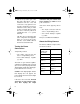
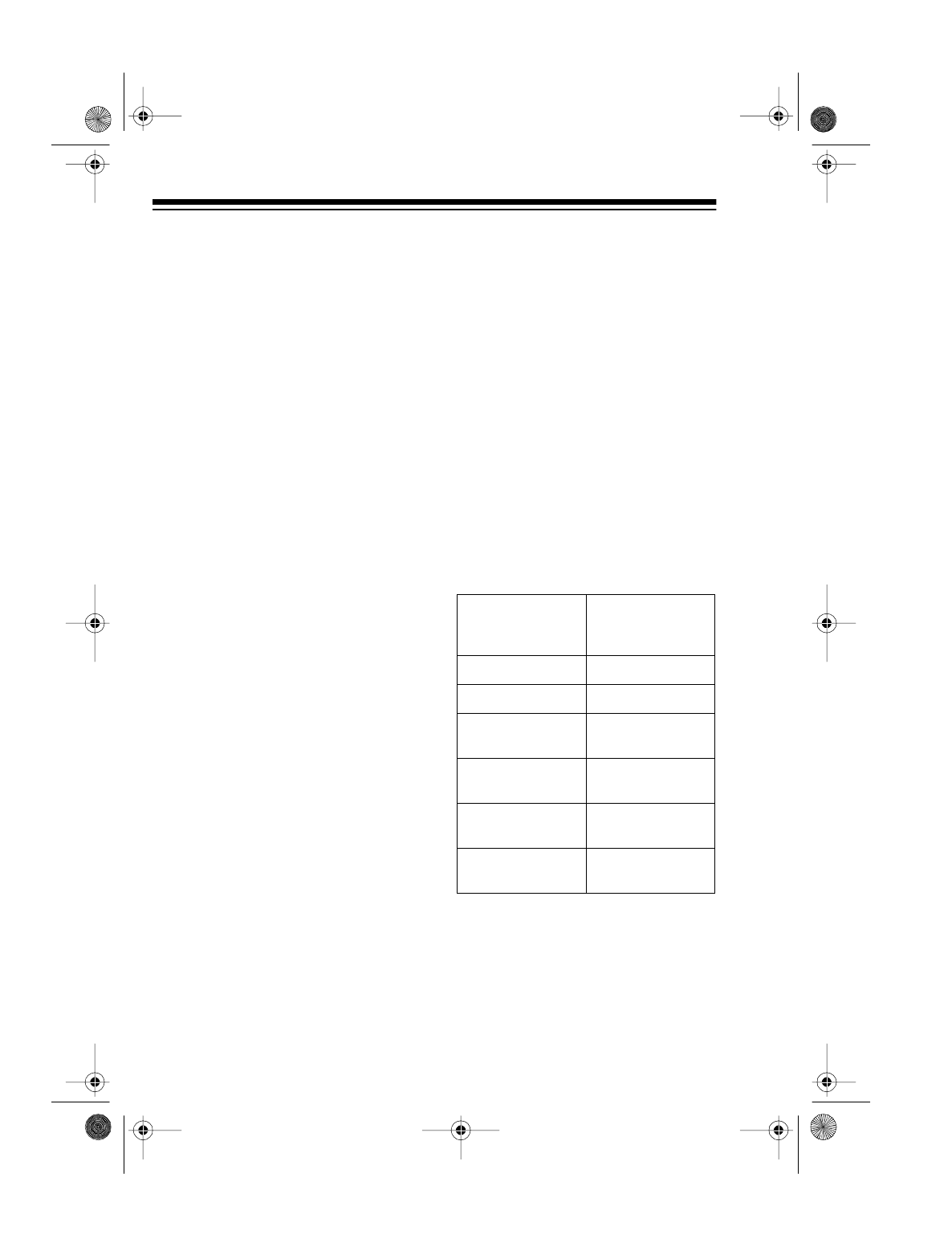
About the Wiring Harness
The harness with the 14-pin connec-
tor has these labels.
SWITCHED
POWER LEAD
500 mA MAX
(NONE)
CLOCK MEMORY (NONE)
POWER LEAD GROUND (–)
SPEAKER REAR
RIGHT (+)
SPEAKER REAR
RIGHT (–)
SPEAKER REAR
LEFT (+)
SPEAKER REAR
LEFT (–)
SPEAKER FRONT
RIGHT (+)
SPEAKER FRONT
RIGHT (–)
SPEAKER FRONT
LEFT (+)
SPEAKER FRONT
LEFT (–)
12-2111.fm Page 8 Wednesday, July 14, 1999 11:50 AM