AUDIO/VIDEO MULTI-CHANNEL RECEIVER RECEPTEUR AUDIOVISUEL A VOIES MULTI-CANAUX RECEPTOR AUDIO-VIDEO MULTICANAL VSX-821-K Register your product on http://www.pioneerelectronics.com (US) http://www.pioneerelectronics.ca (Canada) • Protect your new investment The details of your purchase will be on file for reference in the event of an insurance claim such as loss or theft.
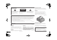
VENTILATION CAUTION IMPORTANT When installing this unit, make sure to leave space around the unit for ventilation to improve heat radiation (at least 40 cm at top, 20 cm at rear, and 20 cm at each side).
This Class B digital apparatus complies with Canadian ICES 003. D8 10 1 3_A1_En Read these instructions. Keep these instructions. Heed all warnings. Follow all instructions. Do not use this apparatus near water. Clean only with dry cloth. Do not block any ventilation openings. Install in accordance with the manufacturer’s instructions. 8) Do not install near any heat sources such as radiators, heat registers, stoves, or other apparatus (including amplifiers) that produce heat.
Thank you for buying this Pioneer product. Please read through these operating instructions so you will know how to operate your model properly. After you have finished reading the instructions, put them away in a safe place for future reference. Contents Before you start . . . . . . . . . . . . . . . . . . . . . . . . . . . . 5 Checking what’s in the box . . . . . . . . . . . . . . . . . . . . . . . . 5 Installing the receiver . . . . . . . . . . . . . . . . . . . . . . . . . . . .
Before you start Please check that you’ve received the following supplied accessories: • Setup microphone • Remote control • AAA size IEC R03 dry cell batteries (to confirm system operation) x2 • AM loop antenna • FM wire antenna • iPod cable • These operating instructions Installing the receiver • When installing this unit, make sure to put it on a level and stable surface.
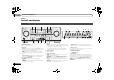
01 Controls and displays Chapter 1: Controls and displays Front panel 1 3 2 4 5 6 2 7 AUD O/ V DEO MULTI- CHANNEL RECE VER MCACC SPEAKERS HDMI DIMMER D SPLAY BAND TUNER ED T AUTO SURROUND/ ALC/ STREAM DIRECT STANDARD SURR ADVANCED SURROUND TUNE VSX 821 16 iPod Phone Pad PRESET 17 18 19 20 18 21 ENTER iPod Phone iPad SOUND RETR EVER AIR DIRECT CONTROL NPUT SELECTOR MASTER VOLUME STANDBY / ON VIDEO 2 INPUT PHONES 5V iPod iPhone MCACC 8 9 10 11 12 2 1A 22 USB 13 3
Controls and displays 11 MCACC SETUP MIC jack Use to connect a microphone when performing Auto MCACC setup (page 20). 12 AUDIO/VIDEO input terminal See Connecting to the front panel video terminal on page 18. 13 iPod iPhone iPad/USB terminal Use to connect your Apple iPod or USB mass storage device as an audio source (page 19). 14 SOUND RETRIEVER AIR When the button is pressed, the input switches to ADAPTER and the listening mode is automatically set to S.R AIR (page 26).
01 Controls and displays Remote control 1 2 3 4 5 11 RECEIVER SLEEP RECE VER 2 RECEIVER Switches the receiver between standby and on. INPUT SELECT INPUT BD DVD TV DVR/BDR CD CD R 12 CH ADAPTER iPod USB VIDEO 1 6 TUNER AUTO/ D RECT BD MENU ALC/ STEREO STANDARD ADV SURR TUNE 8 ENTER HOME MENU SETUP TUNE iPod CTRL 5 Input function buttons Use to select the input source to this receiver (page 22). This will enable you to control other components with the remote control (page 40).
Controls and displays 10 Number buttons and other component controls Use the number buttons to directly select a radio frequency (page 28) or the tracks on a CD, etc. There are other buttons that can be accessed after RECEIVER is pressed. (For example MIDNIGHT, etc.) HDD*, DVD*, VCR* – These buttons switch between the hard disk, DVD and VCR controls for HDD/DVD/VCR recorders. S.RETRIEVER – Press to restore CD quality sound to compressed audio sources (page 30).
02 Connecting your equipment Chapter 2: Hints on the speaker placement Connecting your equipment Placing the speakers By connecting the left and right front speakers (L/R), the center speaker (C), the left and right surround speakers (SL/SR), and the subwoofer (SW), a 5.1 ch surround system can be enjoyed. Further, by using an external amplifier, you can connect the left and right surround back speakers (SBL/SBR) or the left and right front height speaker (FHL/FHR) to boost your system up to a 7.
Connecting your equipment 02 The receiver will work with just two stereo speakers (the front speakers in the diagram) but using at least three speakers is recommended, and a complete setup is best for surround sound. Make sure you connect the speaker on the right to the right (R) terminal and the speaker on the left to the left (L) terminal. Also make sure the positive and negative (+/–) terminals on the receiver match those on the speakers.
02 Connecting your equipment Switching the speaker system Making cable connections Three speaker system settings are possible using the SPEAKERS button. Make sure not to bend the cables over the top of this unit (as shown in the illustration). If this happens, the magnetic field produced by the transformers in this unit may cause a humming noise from the speakers. Use the SPEAKERS button on the front panel to select a speaker system setting.
Connecting your equipment “x.v.Color” and Corporation. are trademarks of Sony Note • When connecting optical cables, be careful when inserting the plug not to damage the shutter protecting the optical socket. • When storing optical cable, coil loosely. The cable may be damaged if bent around sharp corners. • You can also use a standard RCA video cable for coaxial digital connections. About video outputs connection This receiver is not loaded with a video converter.
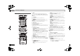
02 Connecting your equipment Connecting a TV and playback components HDMI DN DVR/ BD N OUT V DEO 1 IN COAXIAL IN 1 IN N OPTICAL 1 2 ASSIGNABLE ASS GNABLE (TV SAT) (CD R/TAPE) (CD) Connecting using HDMI Important • If the receiver is connected to a TV using an HDMI cable, the on-screen display (OSD) will not be displayed. Be sure to use a standard RCA analog video cable to connect. In this case, switch the TV input to analog to see the OSD screen (for setup, etc.) on the TV.
Connecting your equipment 02 Connecting a satellite receiver or other digital set-top box This diagram shows connections of a TV and DVD player (or other playback component) with no HDMI terminal to the receiver. • If both TV and player has a component video jacks, you can connect these too. See Using the component video jacks on page 16 for more on this. Satellite and cable receivers, and terrestrial digital TV tuners are all examples of so-called ‘settop boxes’.
02 Connecting your equipment Connecting an HDD/DVD recorder, Blu-ray Disc recorder and other video sources This receiver has audio/video inputs and outputs suitable for connecting analog or digital video recorders, including HDD/DVD recorders and Blu-ray Disc recorders. • Only the signals that are input to the VIDEO IN terminal can be output from the VIDEO OUT terminal. • Audio signals that are input through the digital terminal will not be output from the analog terminal.
Connecting your equipment 02 Connecting optional Bluetooth® ADAPTER Connecting your SiriusConnect™ Tuner The number and kind of connections depends on the kind of component you’re connecting. Follow the steps below to connect a CD-R, MD, DAT, tape recorder or other audio component. • Note that you must connect digital components to analog audio jacks if you want to record to/from digital components (like an MD) to/from analog components. When the Bluetooth ADAPTER (Pioneer Model No.
02 Connecting your equipment Connecting antennas Using external antennas Connecting to the front panel video terminal Connect the AM loop antenna and the FM wire antenna as shown below. To improve reception and sound quality, connect external antennas (see Using external antennas below). To improve FM reception Front video connections are accessed via the front panel using the INPUT SELECTOR or VIDEO2 button on the remote control. There are standard audio/video jacks.
Connecting your equipment 02 Connecting a USB device Plugging in the receiver This receiver has a dedicated iPod terminal that will allow you to control playback of audio content from your iPod using the controls of this receiver. It is possible to listen to two-channel audio using the USB interface on the front of this receiver. Only plug in after you have connected all your components to this receiver, including the speakers.
03 Basic Setup Chapter 3: PRESET RECEIVER VOLUME TOOLS MENU TUNE TV SOURCE CONTROL INPUT SELECT PRESET Basic Setup PARAMETER TOP MENU RECEIVER SLEEP ENTER INPUT Canceling the demo display The display on the front panel shows various information (demo displays) when the receiver is not operating. You can turn off the demo display. For details, see The FL Demo Mode menu on page 37. • The demo mode is canceled automatically when the Auto MCACC setup is performed (see below).
Basic Setup 03 9 Make sure ‘OK’ is selected, then press ENTER. A progress report is displayed on-screen while the receiver outputs test tones to determine the speakers present in your setup. Try to be as quiet as possible while it’s doing this. If the screen in step 7 is left untouched for 10 seconds and ENTER is not pressed in step 8, the Auto MCACC setup will start automatically as shown. 1.Auto MCACC 1.
04 Basic playback Chapter 4: If you selected the proper input source and there is still no sound, select the audio input signal for playback (see Selecting the audio input signal below). Basic playback 4 Press AUTO/DIRECT to select ‘AUTO SURROUND’ and Playing a source Here are the basic instructions for playing a source (such as a DVD disc) with your home theater system.
Basic playback 04 Tip DVR/BDR DVD BD Audio Audio 1. 1. 2. VIDEO 1 CD (CD input) Other than CD input RECEIVER DVR/BDR IN DVD IN BD IN OUT V DEO 1 IN (TV/SAT input) Other than TV/SAT input SIGNAL SEL C1 0 HDMI 2. TV RECEIVER SIGNAL SEL 0 COAXIAL IN 1 (CD) IN OPTICAL 1 2 ASSIGNABLE Audio BD MONITOR TV/SAT OUT IN BD IN DVD CD L IN DVD IN ADAPTER IN IN IN 1 (DVD) 2.
04 Basic playback • If after pressing iPod the display shows NO DEVICE, try switching off the receiver and reconnecting the iPod to the receiver. • The controls of your iPod (excluding the iPod touch and iPhone) will be inoperable when connected to this receiver (Pioneer shows in the iPod display). • Press iPod USB to switch the remote control to the iPod/ USB operation mode.
Basic playback 04 Compressed audio compatibility This receiver’s remote control buttons can be used for basic playback of files stored on USB devices. • Press iPod USB to switch the remote control to the iPod/ USB operation mode. Note that although most standard bit/sampling rate combinations for compressed audio are compatible, some irregularly encoded files may not play back. The list below shows compatible formats for compressed audio files: • MP3 (MPEG-1/2/2.
04 Basic playback Important • Pioneer does not guarantee proper connection and operation of this unit with all Bluetooth wireless technology enabled devices. Remote control operation The remote control supplied with this unit allows you to play and stop media, and perform other operations. • It must be necessary that the Bluetooth wireless technology enabled device supports AVRCP profiles. • Remote control operations cannot be guaranteed for all Bluetooth wireless technology enabled devices.
Basic playback Listening to SIRIUS Radio After connecting, you will be able to use this receiver to select channels using the front panel display. Note • In order to activate your radio subscription, you will need the SIRIUS ID (SID) which uniquely identifies your tuner. The SID may be found on a sticker located on the packaging, or on the bottom of the tuner itself. The label will have a printed 12-digit SID number.
Basic playback Listening to the radio Saving station presets Listening to station presets The following steps show you how to tune in to FM and AM radio broadcasts using the automatic (search) and manual (step) tuning functions. Once you are tuned to a station you can memorize the frequency for recall later—see Saving station presets below for more on how to do this.
Listening to your system Choosing the listening mode This receiver offers a variety of listening modes to accommodate playback of various audio formats. Choose one according to your speaker environment or the source. While listening to a source, press the listening mode button repeatedly to select a listening mode you want.
05 Listening to your system a. If surround back channel processing (page 31) is switched off, or the surround back speakers are set to NO, DOLBY PLIIx becomes DOLBY PLII (5.1 channel sound). b. You can also adjust the C.WIDTH, DIMEN., and PNRM. effect (see Setting the Audio options on page 32). c. You can also adjust the H.GAIN effect (see Setting the Audio options on page 32). d. You can also adjust the C.IMG effect (see Setting the Audio options on page 32). e.
Listening to your system 05 Using surround back channel processing Setting the Up Mix function This receiver’s Phase Control feature uses phase correction measures to make sure your sound source arrives at the listening position in phase, preventing unwanted distortion and/or coloring of the sound. Phase Control technology provides coherent sound reproduction through the use of phase matching for an optimal sound image at your listening position.
05 Listening to your system Setting/What it does Setting the Audio options There are a number of additional sound settings you can make using the AUDIO PARAMETER menu. The defaults, if not stated, are listed in bold. Important • Note that if a setting doesn’t appear in the AUDIO PARAMETER menu, it is unavailable due to the current source, settings and status of the receiver.
Listening to your system PNRM. (Panorama)i Extends the front stereo image to include surround speakers for a ‘wraparound’ effect. Option(s) OFF ON 0 to 10 C.IMG (Center Image)j Default: 3 (Applicable only when using a center speaker) (NEO:6 MUSIC), Adjust the center image to create a wider 10 (NEO:6 stereo effect with vocals. Adjust the effect CINEMA) from 0 (all center channel sent to front right and left speakers) to 10 (center channel sent to the center speaker only). H.
06 The System Setup menu 4 Select the setting you want to adjust. Chapter 6: The System Setup menu Using the System Setup menu The following section shows you how to make detailed settings to specify how you’re using the receiver, and also explains how to fine-tune individual speaker system settings to your liking. Important • The OSD will not appear if you have connected using the HDMI output to your TV. Use component or composite connections for system setup.
The System Setup menu Note • If you select SMALL for the front speakers, the subwoofer will automatically be fixed to YES. Also, the center, surround, surround back and front height speakers can’t be set to LARGE if the front speakers are set to SMALL. In this case, all bass frequencies are sent to the subwoofer. • If the surround speakers are set to NO, the surround back speakers will automatically be set to NO.
06 The System Setup menu 5 Adjust the level of each channel using /. If you selected Manual, use / to switch speakers. The Auto setup will output test tones in the order shown onscreen: 2c.Channel Level Front L Center Front R Surround R Surr. Back R Surr. Back L Surround L Subwoofer [ [ [ [ [ [ [ 0dB 0dB] 0dB] 0dB] ] ] 0dB] 0dB] Return Adjust the level of each speaker as the test tone is emitted.
The System Setup menu 06 Specify either using the surround back speaker or the front height speaker connection with the PRE OUT SURR BACK/ FRONT HEIGHT outputs. An additional amplifier is required for the speaker connection. • Default setting: Surr. Back 1 Select ‘Pre Out Setting’ from the System Setup menu. System Setup 4.Pre Out Setting 1 . Auto MCACC 2 . Manual SP Setup 3 . Input Assign 4 . Pre Out Setting 5 . HDMI Setup 6 . Auto Power Down 7 . FL Demo Mode Pre Out Surr.
07 Control with HDMI function Chapter 7: Control with HDMI function Synchronized operations below with a Control with HDMIcompatible Pioneer TV or Blu-ray Disc player or with a component of another make that supports the Control with HDMI functions are possible when the component is connected to the receiver using an HDMI cable. • Synchronized amp mode The receiver’s volume can be set and the sound can be muted using the TV’s remote control.
Control with HDMI function When a TV supporting the HDMI Audio Return Channel function is connected to the receiver, the sound of the TV can be input via the HDMI terminal. • ON – The TV’s sound is input via the HDMI terminal. This can only be selected when Control is set to ON. • OFF – The TV’s sound is input from the audio input terminals other than HDMI inputs. 7 When you’re finished, press RETURN. You return to the System Setup menu.
08 Controlling the rest of your system Chapter 8: Controlling the rest of your system Selecting preset codes directly RECEIVER SLEEP TV SOURCE CONTROL HDD DVD VCR 1 2 3 S RETR EVER SB CH CH SELECT 4 RECEIVER INPUT SELECT Most components can be assigned to one of the input function buttons using the component’s manufacturer preset code stored in the remote.
Controlling the rest of your system 08 Function TV Button(s) Satellite/ Cable TV This remote control can control these components (BD, DVD, CD, DVR (BDR), VCR, CD-R) after entering the proper codes or teaching the receiver the commands (see Controlling the rest of your system on page 40 for more on this). Use the input function buttons to select the component.
08 Controlling the rest of your system TV Pioneer 0291, 0113, 0294, 0296 Admiral 0001, 0014 Adventura 0012 Aiwa 0002 Akai 0002, 0100 Albatron 0097 Alleron 0009 America Action 0104 Amtron 0008 Anam 0104 Anam National 0003, 0008 AOC 0004, 0005, 0006, 0100 Apex 0021, 0102, 0106 Audiovox 0008, 0104 Aventura 0103 Axion 0094 Bang & Olufsen 0111 Belcor 0004 Bell & Howell 0001 Benq 0064 Bradford 0008, 0104 Brillian 0109 Brockwood 0004 Broksonic 0104 Candle 0004, 0006, 0012, 0100 Carnivale 0100 Carver 0101 CCE 011
Controlling the rest of your system Marta 1003 Media Center PC 1017 MEI 1004 Memorex 1001, 1002, 1003, 1004, 1005, 1018, 1019 MGN Technology 1002 Microsoft 1017 Mind 1017 Mitsubishi 1010 Motorola 1004 MTC 1002 Multitech 1002, 1005 NEC 1000, 1001 Nikko 1003 Niveus Media 1017 Noblex 1002 Northgate 1017 Olympus 1004 Optimus 1003 Orion 1014, 1019 Panasonic 1004, 1008 Philco 1004 Philips 1004, 1011, 1016, 1020, 1022, 1023, 1024, 1025 Philips Magnavox 1011 Pilot 1003 Proscan 1030 Pulsar 1018 Quarter 1001 Quartz 1
09 Additional information Chapter 9: Additional information Troubleshooting Incorrect operations are often mistaken for trouble and malfunctions. If you think that there is something wrong with this component, check the points below. Take a look at the other components and electrical appliances being used, because sometimes the problem may lie there.
Additional information Check that pairing is correct. The pairing setting was deleted from this unit or the Bluetooth wireless technology device. Reset the pairing. Check that the profile is correct. Use a Bluetooth wireless technology device that supports A2DP profile and AVRCP profile. HDMI No picture or sound. If the problem still persists when connecting your HDMI component directly to your monitor, please consult the component or monitor manual or contact the manufacturer for support.
09 Additional information Note • Depending on the component, audio output may be limited to the number of channels available from the connected display unit (for example audio output is reduced to 2 channels for a monitor with stereo audio limitations). • If you want to switch the input source, you’ll have to switch functions on both the receiver and your display unit.
Additional information 09 Amplifier section Continuous average power output of 80 watts* per channel, min., at 8 ohms, from 20 Hz to 20 000 Hz with no more than 0.08 %** total harmonic distortion. Front (stereo) . . . . . . . . . . . . . . . . . . . . . . . . . . 80 W + 80 W Power output (1 kHz, 8 Ω, 0.05 %) . . . . . . 110 W per channel Guaranteed speaker impedance FRONT:A, B. . . . . . . . . . . . . . . . . . . . . . . . . . . . . 6 Ω to 16 Ω FRONT:A+B . . . . . . . . . . . . . . . . . . . . . . . . . .
PIONEER ELECTRONICS (USA) INC. PIONEER ELECTRONICS OF CANADA, INC. LIMITED WARRANTY WARRANTY VALID ONLY IN COUNTRY OF PRODUCT PURCHASE WARRANTY Pioneer Electronics (USA) Inc. (PUSA), and Pioneer Electronics Of Canada, Inc. (POC), warrant that products distributed by PUSA in the U.S.A.
PIONEER ELECTRONICS (USA) INC. PIONEER ELECTRONIQUES DU CANADA, INC. GARANTIE LIMITÉE GARANTIE VALIDE SEULEMENT DANS LE PAYS OU LE PRODUIT A ÉTÉ ACHETÉ GARANTIE Pioneer Electronics (USA) Inc. (PUSA) et Pioneer Électronique du Canada, Inc.
VSX-821_UCSMXCN_En.book 50 ページ 2010年12月21日 火曜日 午後5時19分 To register your product, find the nearest authorized service location, to purchase replacement parts, operating instructions, or accessories, please go to one of following URLs : Pour enregistrer votre produit, trouver le service après-vente agréé le plus proche et pour acheter des pièces de rechange, des modes d’emploi ou des accessoires, reportez-vous aux URL suivantes : In the USA/Aux Etats-Unis http://www.pioneerelectronics.
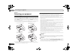
Preventing shorting of speaker cords If the speaker cords short (touch each other or the metal casing), you will not only lose the sound from the speakers, but the system may also be damaged as a result. Please read the guidelines below carefully and take care to connect the speaker cords correctly. When connecting the speakers, make sure that the exposed wire of each speaker cord does not touch anything other than the correct speaker terminal.