
Operating instructions


22 Choosing a Ham Radio
but have lower efficiency than mounts attached directly to the vehicle and can be knocked
loose. If you purchase the mount separately from the antenna, make sure the mount and
antenna have the same type of mechanical connection!
The most popular antenna feed line is coaxial cable or coax. There are many types, but
the most common are (from smallest to largest) are RG-58, RG-8X, and RG-8 or RG-213.
Use RG-58 only for short (50 feet or less) distances due to its higher losses and never at the
output of an amplifier. RG-8X will carry the full legal power, but is not a good choice for
feed lines longer than 100 feet or mistuned antennas. RG-213 is suitable for all amateur HF
uses, except for extremely long feed lines. At HF, the standard connectors are the “UHF”
connector family’s PL-259 (cable plug) and SO-239 (equipment receptacle) illustrated in
the VHF section. Cable is available with connectors pre-installed or with a little “Elmer-
ing” you can learn how to install them yourself as described on the ARRL TIS Web site.
The other type of feed line is open-wire, ladder, or window line consisting of two paral-
lel wires coated with plastic insulation. Open-wire line has very low losses, but is not as
convenient to use as coaxial cable and requires an antenna tuner or some other kind of
impedance transformer to work with most HF radios along with a parallel-to-coaxial balun
so that you can connect the feed line to the radio.
Accessories & Special Features
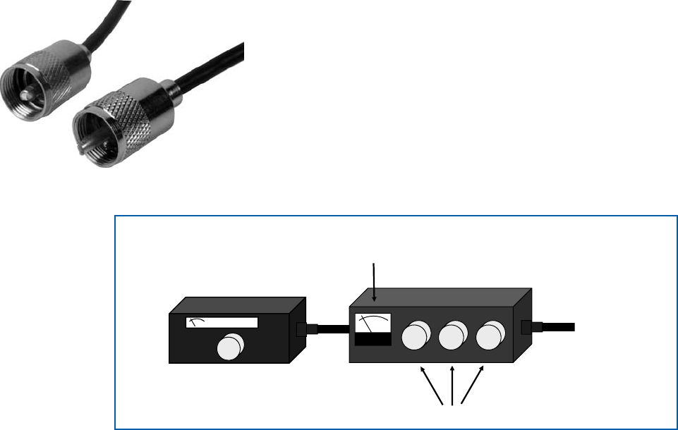
Antenna tuners are known by several names; impedance matching unit, tuning unit,
matchbox, transmatch, etc. They do not actually tune the antenna, but convert whatever im-
pedance is presented by the antenna system at the input to the feed line into a 50-ohm load
so that your transmitter will deliver maximum power output. Some radios have an auto-
matic antenna tuner or ATU built-in, but if yours doesn’t and your antenna’s SWR is much
higher than 2:1 on a frequency you wish to use, then you’ll need an
external antenna tuner, either automatic or manually-adjusted. A
model rated at 300 watts will accommodate the output of a 100-watt
transceiver with room to spare. Manual antenna tuners often include
an SWR meter or directional wattmeter, but these can also be pur-
chased as individual items and are very handy shack accessories.
An SWR meter can be used as an antenna system test instrument or
to monitor the state of an antenna. Directional wattmeters measure
the power flowing back and forth in your feed line and may also be
calibrated to show SWR. Both power and SWR meters are designed
to be used at either HF or VHF and will provide uncalibrated read-
Figure11
28.385
Impedance Adjustments
SWR and Power
Meter Built-in
To Antenna
Antenna Tuner
Figure11—Antenna tunersareknownbyseveralnames;impedance matching unit, tun-
ing unit, matchbox, transmatch,etc.Theyconvertwhateverimpedanceispresentedbythe
antennasystemattheinputtothefeedlineintoa50-ohmloadsothatyourtransmitterwill
delivermaximumpoweroutput.
Twoso-called“UHF”(PL-259)coaxial
cableconnectors.