
Owner`s manual

49
3. Set the input coupling switch to
GND
.
4. Connect the
GROUND
(0 volt) wire to the signal
source’s ground or reference level.
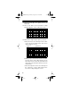
5. Rotate
Zero Level
to vertically position the trace to
a convenient line on the grid overlay.
Caution
: To avoid an overload when measuring
AC, make sure the zero line is centered vertically
on the grid overlay.
Note
: If the trace is widened by stray interference,
ground the probe body near the point being mea-
sured. The trace position is the voltage reference
line and all voltage measurements are read in
respect to this line. (Do not adjust the vertical
positioning control after the reference is estab-
lished.)
6. If it was necessary to ground the tip (see Step 5
note), remove the tip from the ground or reference
voltage. This readies the tip so you can use it to
make a measurement.
7. Set the input coupling selector to
AC
or
DC
(depending on the voltage you want to measure).
8. Set the input voltage range to the appropriate
1V
,
10V
, or
100V
range scale.
Cautions
:
• Always set the selector to the highest range
when you are not sure of the voltage to be
measured.
• Never exceed 100 Volts AC (peak-to-peak) or
DC between the measured test point and
ground.
22-310.fm Page 49 Friday, August 6, 1999 12:26 PM