
Owner`s manual

45
Note: If the trace is widened by stray interference,
ground the probe body near the point being mea-
sured. The trace position is the voltage reference
line and all voltage measurements are read in
respect to this line. (Do not adjust the vertical
positioning control after the reference is estab-
lished.)
5. If it was necessary to ground the tip (see Step 4
note), remove the tip from the ground or reference
voltage. This readies the tip so you can use it to
make a measurement.
6. Set the input coupling switch to
AC
.
7. Press the Select button to set the trigger mode to:
•
+ EXTERN
(if you want to trigger on the incom-
ing signal’s rising edge), or
•
– EXTERN
(if you want to trigger on the incom-
ing signal’s falling edge).
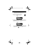
8. Press the Menu button so
TRIGGER LEVEL
appears on the ProbeScope’s display.
9. Continuously press the Select button until you set
the trigger level as desired.
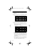
Note: The trigger level you select sets the level of
the incoming waveform that causes the Probe-
Scope to begin reading the signal. The Probe-
Scope shows the trigger level on the left side of
the LCD.
10. Press the Menu button until the
MODE
screen
appears on the ProbeScope’s display.
11. Press the Select button so
SINGLE
appears on
the ProbeScope’s display.
12. Press the Menu button so
WAITING!
appears
on the ProbeScope’s display.
22-310.fm Page 45 Friday, August 6, 1999 12:26 PM