
Owner`s manual

41
Measuring Phase
Follow these steps to measure the phase difference
between two signals.
1. Set the input coupling switch to
GND
.
2. Connect the
GROUND
(0 volt) wire to the signal
source’s ground or reference level.
3. Rotate
Zero Level
to vertically center the trace on
the grid overlay.
Note
: If the trace is widened by stray interference,
ground the probe body near the point being mea-
sured.
The trace position is the voltage reference line
and all voltage measurements are read in respect
to this line. (Do not adjust the vertical positioning
control after the reference is established.)
4. If it was necessary to ground the tip (see Step 3
note), remove the tip from the ground or reference
voltage. This readies the tip so you can use it to
make a measurement.
5. Set the input coupling switch to
AC
.
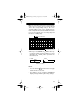
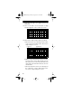
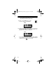
6. Click on the vertical cursor icon
to display the vertical cursors.
The
Time
:
box appears below
the grid display.
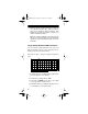
7. Apply the ProbeScope’s tip to
the first signal source, then click
on the oscilloscope hold icon.
8. Measure the slope of the first circuit as follows:
a.Place the mouse cursor directly over the oscillo-
scope screen’s left vertical cursor. The cursor’s
shape changes to a cross.
—
HOLD
22-310.fm Page 41 Friday, August 6, 1999 12:26 PM