
Owner`s manual

37
a.Place the mouse cursor directly over the oscillo-
scope screen’s left vertical cursor. The cursor’s
shape changes to a cross.
b.While you press and hold the left mouse button,
move the mouse left or right until the screen’s
left vertical cursor touches a point where the ris-
ing or falling edge of the waveform intersects
with the zero reference line.
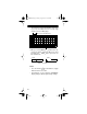
7. Apply the probe tip to the signal
source, then click on the oscillo-
scope hold icon.
8. Measure the horizontal distance between rising or
falling points on the displayed waveform as fol-
lows:
a.Place the mouse cursor directly over the oscillo-
scope screen’s right vertical cursor. The cur-
sor’s shape changes to a cross.
b.While you press and hold the left mouse button,
move the mouse left or right until the screen’s
right vertical cursor touches the next point
where the waveform’s rising or falling edge
intersects with the zero reference line.
Note: To avoid inaccurate frequency measure-
ments, make sure you set the cursors in Steps
6b and 8b to two consecutive rising or two con-
secutive falling points of a displayed waveform.
HOLD
22-310.fm Page 37 Friday, August 6, 1999 12:26 PM