
Owner`s manual

31
4. If it was necessary to ground the tip (see Step 3
note), remove the tip from the ground or reference
voltage. This readies the tip so you can use it to
make a measurement.
5. Set the input coupling switch to
AC
.
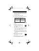
6. If you know the level of the signal to be measured,
set the input voltage switch as follows.
Note:
If you do not know the level of the signal to
be measured, always set the input voltage switch
to
100V
.
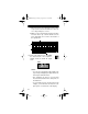
7. Click on the horizontal cursor icon
to display the horizontal cursors.
The
Volt
:
box appears below
the grid display.
a.Place the mouse cursor directly over the oscillo-
scope screen’s upper horizontal cursor. The
cursor’s shape changes to a cross.
b.While you press and hold the left mouse button,
move the mouse up or down until the screen’s
upper horizontal cursor touches the top of the
signal peaks.
8. Apply the probe tip to the signal
source, then click on the oscillo-
scope hold icon.
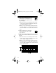
9. Measure the vertical distance between the posi-
tive and negative peaks as follows:
Switch Position Measures
1V
10V
100V
0.00 – 1.00 V
0.0 – 10.0 V
0 – 100 V
—
HOLD
22-310.fm Page 31 Friday, August 6, 1999 12:26 PM