
Owner`s manual


26
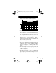
7. Set the input coupling switch to
DC
. The selected
setting appears on your computer’s monitor.
8. If you know the level of the signal to be measured,
set the input voltage switch as follows.
Note:
If you do not know the level of the signal to
be measured, always set the input voltage switch
to
100V
.
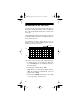
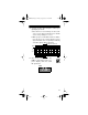
9. Click on the horizontal cursor icon
to display the horizontal cursors.
The
Volt
:
box appears below
the grid display.
a.Place the mouse cursor directly over the oscillo-
scope screen’s lower horizontal cursor until the
cursor’s shape changes to a cross.
b.While you press and hold the left mouse button,
move the mouse up or down until the screen’s
lower horizontal cursor is superimposed directly
on the reference line.
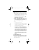
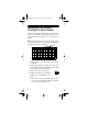
10. Apply the probe tip to the signal source. The oscil-
loscope grid display vertically displaces the DC
signal’s flat-line away from the zero reference
line.
11. Click on the oscilloscope hold icon.
Switch Position Measures
1V
10V
100V
0.00 – 1.00 V
0.0 – 10.0 V
0 – 100 V
—
HOLD
22-310.fm Page 26 Friday, August 6, 1999 12:26 PM