
User's Manual
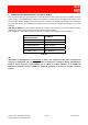
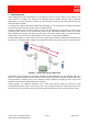
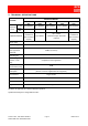
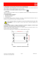
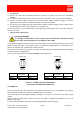
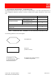
Table Of Contents

91 080 0730F - OR2-SBLP1 SERIES Page 8 ENG Edit. 02
FIXED BAND OFF-AIR REPEATERS
• Connections
A) Connect the cable from the outdoor antenna to connector N (f) BTS side, ref. 4 (ILL OR2-SBLP1
SERIES).
B) Connect the cable from the indoor antenna to connector N (f) MS side, ref. 7 (ILL OR2-SBLP1 SERIES).
C) Connect the power supply connector for the external AC/DC adapter (standard supply) to the power
supply socket connector of the equipment, ref. 1 (ILL OR2-SBLP1 SERIES).
D) Connect the power supply plug of the external AC/DC adapter (standard supply) to the line power source
corresponding to the specs of the equipment (i.e. 100-230V A.C.).
For the connections, it is recommended that an RF cable having characteristics similar to the RFS cable type
LCF14-50, be used.
• How to set the repeater gain
PLEASE REMEMBER:
It is strongly recommended to set the repeater gain at maximum level. Attenuation should
be set only if antenna isolation is not enough (less than 75dB).
The OR2-SBLP1 SERIES equipment comes with selectors which permit separately adjusting the gain for both
up-link and down-link paths. The maximum gain for the equipment is 60dB (typical). The attenuation of the
gain can be adjusted in the 0÷30dB range with steps of 1dB.
The variations to be made to the gain on the up-link and down-link paths are determined during link budget
calculation stage (ref. paragraph 4.1).
Please set the gain as shown in FIGURE 3 (Example of gain adjustment).
FIGURE 3 – EXAMPLE OF GAIN ADJUSTMENT
ON THE UP-LINK AND DOWN-LINK PATHS
4.3. POWER-UP
Once all connections have been performed and the gain has been set, turn on the equipment by moving the
switch indicated with ref. 3 (ILL OR2-SBLP1 SERIES) to the “ON” position.
Green LED, ref. 2 (ILL OR2-SBLP1 SERIES), will light up to indicate the presence of the power supply
voltage.
Also by using the mobile phone, make sure that the RF signal is available and adequate in the area of
equipment coverage.
If there should be problems, please refer to the following paragraph (troubleshooting).
DOWN-LINK
UP-LINK
- 16 - 8 - 4 - 2 - 1
ON
OFF
ON
OFF
Path Attenuation
(see Figure)
Gain
Down-link 0dB 60dB
Up-link 0dB 60dB
DOWN-LINK
UP-LINK
- 16 - 8 - 4 - 2 - 1
OFF
ON
OFF
ON
Path Attenuation
(see Figure)
Gain
Down-link 20dB 40dB
Up-link 25dB 35dB