
User's Manual
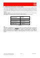
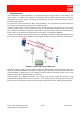
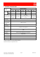
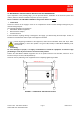
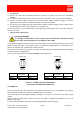
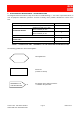
Table Of Contents

91 080 0730F - OR2-SBLP1 SERIES Page 7 ENG Edit. 02
FIXED BAND OFF-AIR REPEATERS
4.2. MECHANICAL AND ELECTRICAL INSTALLATION OF THE REPEATER
Upon completion of the planning stage, you can proceed with the installation of the antennas (indoor and
outdoor) and then with the installation and power-up of the repeater.
Please remember: the OR2-SBLP1 SERIES is designed for indoor use ONLY
.
• Initial check
Check the contents of the supply in terms on its completeness and/or eventual damage undergone by the
material during transport.
The materials included in the supply are:
• OR2-SBLP1 SERIES equipment,
• External AC/DC adapter,
• Technical manual.
If there should be anything missing or damaged in the supply, you should notify the Sales Dept. of RFS, to
facilitate the reinstatement and/or repair of the equipment involved.
Before beginning installation of the equipment, make sure that ON/OFF switch, ref. 3 (ILL OR2-
SBLP1 SERIES), is in the OFF position. The green LED, ref. 2 (ILL OR2-SBLP1 SERIES), must
be turned off.
• Positioning
To avoid damages to people, it is highly recommended to install the equipment at 2.5metres high
positioning, in order to prevent electric shock caused by contact.
Position the OR2-SBLP1 SERIES equipment and fix its position with the four M4 bolts, which are to be
inserted in the pre-cut slots, ref. A (FIGURE 2).
Check the correct positioning of the equipment before completely tightening the bolts.
FIGURE 2 – POSITION OF THE PRE-CUT SLOTS
DOWN-LINK
UP-LINK
- 16 - 8 - 4 - 2 - 1
206 mm (8.11 in.)
90 mm (3.54 in.)
AA
AA