
User's Manual
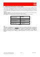
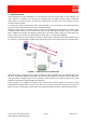
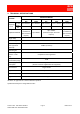
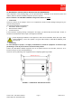
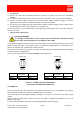
Table Of Contents

91 080 0730F - OR2-SBLP1 SERIES Page 3 ENG Edit. 02
FIXED BAND OFF-AIR REPEATERS
2. OPERATING MODE
Off-Air Repeaters for indoor applications are connected, by means of coaxial cables, to two antennas. The
‘donor antenna’, an outdoor one, interfaces the equipment with the Mobile Operator’s Base Transceiver
Station (BTS). The ‘service antenna’, an indoor one, empowers the coverage of the indoor dead spot, and so it
interfaces mobile terminals.
The signal to be enhanced follows two distinct paths (FIGURE 1). The up-link path, from mobile terminals to
the BTS, and the down-link path, from the BTS to mobile terminals.
Along the down-link path, the outdoor antenna receives the signal from the BTS and then, by means of the
connecting cable, delivers it to the repeater BTS connector (ILL OR2-SBLP1 SERIES, ref. 4). The repeater
filters, amplifies and transmits the signal by feeder cable to the indoor antenna “filling” the indoor dead spot.
Indoor antenna is connected to the repeater MS connector (ref. 7, ILL OR2-SBLP1 SERIES).
Along the up-link path, the indoor antenna receives the signal from the mobile terminals (MS) and delivers it to
the repeater. The repeater filters, amplifies and transmits the signal by the outdoor antenna to Operator’s BTS.
FIGURE 1 – DOWN-LINK and UP-LINK PATHS
OR2-SBLP1 series repeaters have got built-in attenuators to allow adjustable gain. DIP-switches (ref. 5 and
ref. 6, ILL OR2-SBLP1 SERIES) are available to adjust the gain separately for up-link and down-link paths.
During installation, equipment gain can be adjusted to reduce interference towards the BTS and to avoid
problems related with the isolation between the antennas.
During operation, the equipment Automatic Level Control (ALC) protects against the emission of high
intermodulation products, both in case that the user is in the nearby vicinity of the indoor antenna (ALC up-
link) and in case of a temporary level increase of the signal coming from the donor antenna (ALC down-link).