
User's Manual
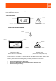
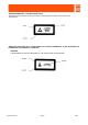
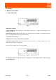
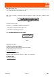
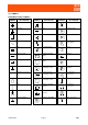
Table Of Contents

STANDARDS Page 7 ENG
2.2) SYMBOLS
EQUIPMENT FRONT SYMBOLS
SYMBOLS DESCRIPTION SYMBOLS DESCRIPTION SYMBOLS DESCRIPTION
Earth connection Impulsive command Band-stop filter
Ground Fuse Low-pass filter
Chassis ground Thermal breaker High-pass filter
AC Failure Modulator,
demodulator
DC Overtemperature Stereo
Pulse current Output monitoring
signal
Balance
Battery / accumulator Input monitoring
signal
Amplifier
Positive connector
P
Direct power
monitoring socket
Adjustable gain
amplifier
Negative connector
P
Reflected power
monitoring socket
Loudspeaker
connection
OFF
L.O.
Local oscillator
monitoring socket
Audio connection
ON Gating as opening
criterion
Headphone
connection
STAND-BY Gating as closing
criterion
Stereo headphone
ON push-button Channel / band filter Star connection