FIXED BAND OFF-AIR REPEATERS OR2-SBLP1 SERIES Doc. code 91 080 0730F - Rel. 02 TECHNICAL HANDBOOK Radio Frequency Systems Kabelkamp 20 30179 Hannover, Germany Tel.: +49 511 676 2731 Fax: +49 511 676 2515 E-mail: sales.europe@rfsworld.
INDEX 1. FIXED BAND OFF-AIR REPEATERS - OR2-SBLP1 SERIES.................................................................... 2 2. OPERATING MODE ..................................................................................................................................... 3 3. TECHNICAL SPECIFICATIONS .................................................................................................................. 4 4. PROCEDURES FOR INSTALLATION AND POWER-UP ..................................
1. FIXED BAND OFF-AIR REPEATERS - OR2-SBLP1 SERIES Over the past decade, the growing diffusion of portable terminals has created the need for capillary coverage of the territory. Telecommunications networks must permit coverage services throughout the territory in the most extensive manner possible and, at the same time, guarantee the reliability and quality of the connection. From this point of view, the availability and quality of the services must be also guaranteed indoors, i.e. inside buildings.
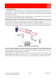
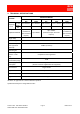
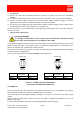
2. OPERATING MODE Off-Air Repeaters for indoor applications are connected, by means of coaxial cables, to two antennas. The ‘donor antenna’, an outdoor one, interfaces the equipment with the Mobile Operator’s Base Transceiver Station (BTS). The ‘service antenna’, an indoor one, empowers the coverage of the indoor dead spot, and so it interfaces mobile terminals. The signal to be enhanced follows two distinct paths (FIGURE 1).
3.
4. PROCEDURES FOR INSTALLATION AND POWER-UP • Before installing, carefully read the safety norms herewith attached. • The equipment must be connected to ancillaries specifically designed for the standard in use and the band to be enhanced. • The OR2-SBLP1 SERIES has been designed for indoor use only. Changes in temperature and humidity can influence the reliability of the equipment. The best place to install the equipment is a tempered and well-ventilated environment.
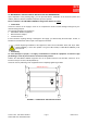
• Isolation between the antennas Since the equipment is a bi-directional amplifier, the isolation between the outdoor antenna (donor) and the indoor antenna (service) must be at least 15dB greater that the repeater gain. For example, if the repeater gain is 60dB, the minimum isolation between both antennas must be greater than 75dB. To guarantee the correct isolation between the antennas, it is necessary to plan for an adequate distance between them, both horizontally and vertically.
4.2. MECHANICAL AND ELECTRICAL INSTALLATION OF THE REPEATER Upon completion of the planning stage, you can proceed with the installation of the antennas (indoor and outdoor) and then with the installation and power-up of the repeater. Please remember: the OR2-SBLP1 SERIES is designed for indoor use ONLY. • Initial check Check the contents of the supply in terms on its completeness and/or eventual damage undergone by the material during transport.
• Connections A) Connect the cable from the outdoor antenna to connector N (f) BTS side, ref. 4 (ILL OR2-SBLP1 SERIES). B) Connect the cable from the indoor antenna to connector N (f) MS side, ref. 7 (ILL OR2-SBLP1 SERIES). C) Connect the power supply connector for the external AC/DC adapter (standard supply) to the power supply socket connector of the equipment, ref. 1 (ILL OR2-SBLP1 SERIES).
5. EXTRAORDINARY MAINTENANCE – TROUBLESHOOTING The diagrams below describe the steps to be taken in troubleshooting, i.e. the series of operations which, in case of equipment malfunction, permit the end-user to identify, and if possible, eliminate the causes of the fault. PROBLEM ENCOUNTERED STEP GREEN LED (ref. 2, ILL OR2-SBLP1 SERIES) IS OFF GREEN LED (ref. 2, ILL OR2SBLP1 SERIES) IS OFF GREEN LED (ref.
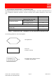
PROCEDURE 1 PROBLEM GREEN LED (ref. 2, ILL OR2-SBLP1 SERIES) IS OFF START Does the equipment guarantee service just the same? no REFERENCE TO THE PROCEDURE 2 yes The LED is broken. The equipment can just the same extend the signal. END 91 080 0730F - OR2-SBLP1 SERIES FIXED BAND OFF-AIR REPEATERS Page 10 ENG Edit.
PROCEDURE 2 NO ’INDOOR’ SIGNAL PROBLEM The GREEN LED (ref. 2, ILL OR2-SBLP1 SERIES) IS OFF START Is the ext. AC/DC adapter connected to the equipment? (connector ref. 1, ILL OR2-SBLP1 SERIES) yes Is the ext. AC/DC adapter plugged into the line voltage? no Connect the ext. AC/DC adapter to the equipment no Connect the ext. AC/DC adapter to the line voltage yes LED = ON? END no no Correct the line voltage problem yes LED = ON? END no yes Does the ext.
PROCEDURE 3 NO INDOOR SIGNAL PROBLEM The GREEN LED (ref. 2, ILL OR2-SBLP1 SERIES) = ON START All connections ok between equipment and the antennas? no Make the connections Signal available? yes Outdoor signal available (> -70dBm)? yes END no yes REFERENCE TO PROCEDURE 4 no Contact the phone company (service provider) to solve the problem. END 91 080 0730F - OR2-SBLP1 SERIES FIXED BAND OFF-AIR REPEATERS Page 12 ENG Edit.
PROCEDURE 4 PROBLEM INDOOR SIGNAL is too WEAK START Outdoor signal level adequate (> -70dBm)? Proper outdoor antenna installed for signal available (ex. Directional antenna)? Antenna positioned and oriented correctly? no yes Install an antenna suited to the outdoor signal available, or change the position and orientation of the outdoor antenna. yes yes Signal available? END no Contact the phone company (service provider) to pinpoint the best signal source.
PROCEDURE 5 INDOOR SIGNAL IS PRESENT, BUT YOU CANNOT MAKE A PHONE CALL PROBLEM START Isolation between outdoor and indoor antennas = more than 15dB greater than repeater gain? no Adjust the horizontal and vertical distance between the antennas until proper indoor/outdoor isolation is achieved.
PROCEDURE 6 PROBLEM INDOOR SIGNAL IS NOT STABLE START Is the outdoor signal stable? no Try to stabilize the RF signal: Find a BTS that provides better reception, or change the position and orientation of the outdoor antenna. yes END Signal stable? no yes Contact the phone company (service provider) to solve the problem.
ATTACHED DOCUMENTS
DC 7V - 16 - 8 - 4 - 2 - 1 OFF/ON 1 2 MS BTS DOWN-LINK 3 UP-LINK 4 5 6 7 ACCESS POINTS MAP Rif./ Ref. 1 2 3 4 5 6 7 DESCRIPTION Vdc input GREEN LED ON: Vdc available ON/OFF switch BTS side N (f) connector UP LINK path gain adjustment DIP Switches DOWN LINK path gain adjustment DIP Switches MS side N (f) connector Part Number Date Title ILL OR2-SBLP1 SERIES OR2-SBLP1 SERIES ACCESS POINTS MAP ED.
1) SAFETY RULES 1.1 Introduction The equipment described in this technical handbook has been designed and tested in conformity of international safety standards IEC215 / EN60215 and IEC950 / EN60950; the equipment has to be used under the responsibility of specialised personnel only. In accordance with IEC215 / EN60215, adjustment, maintenance and repair of the exposed equipment shall be carried out only by qualified personnel, who are aware of the hazards involved.
1.4 Caution and warning statements Caution It's used to indicate the correct operation and maintenance, in order to prevent damage or destruction of equipment or other property. Warning of danger Used to indicate the potential hazard that requires correct procedures or practices in order to avoid personal injury. 1.5 Impaired safety protection Whenever it is likely that safe operation is impaired, the apparatus must be in-operative and secured against unintended operation.
Lay the patient on his back with his arms parallel to his body; if the patient lies on an inclined plane, please make sure that his stomach be slightly lower than his breast. Open the patient's mouth and check if there are foreign bodies. Kneel down near the patient at the same level as his head's, put one of your hands under his head and the other one under his neck. Lift the patient's neck and let his head fall backwards the most possible.
ANNEX 1 When the equipment or the modules are equipped with the labels as shown here below, it is essential to observe the warnings contained -LIVE VOLTAGE POINT -PROTECTIVE EARTHING TERMINAL BLACK -CLASS 1 LASER PRODUCT BLACK BLACK YELLOW BLACK YELLOW EXPLANATORY LABEL (affixed to the CLASS 1 product side) WARNING LABEL (affixed to the CLASS 1 product front) Products which are of CLASS 1 as defined in the IEC EN 60825-1, fourth edition “Safety of laser products -Part 1: Equipment classification, r
-DEVICES SENSITIVE TO THE ELECTROSTATICS WARNING: Please observe the due precautions in handling devices which are sensitive to the electrostatics. -NON-SOLID ELECTROLYPTIC CAPACITORS MAY CONTAIN CHEMICALS TO BE REGARDED AS HAZARDOUS, IF INCORRECTLY HANDLED.
2) STANDARDS 2.1. MANUFACTURE LABELS 2.1.1 BAR CODE LABEL Fig. 1 Label fields (ref. Fig.1): a) Serial number: this field contains the serial number (made up of a 7-digit sequential group) of the module or equipment. b) F (final test tracing out): this field contains an F letter that has been barred to certify that the item has been successfully tested in the factory Final Test Dept. c) Customer order reference. d) Equipment acronym or manufacture part number.
2.1.2 MANUFACTURE LABELS FOR RACK CABINETS AND EQUIPMENT (1) (4) (9) (5) (2) (6) (10) (3) (7) (8) (11) 90mm Fig. 3 Label fields (ref. Fig.3): (1) SYSTEM (it will be filled in only if the rack cabinet or the equipment belong to a system): this field contains the system acronym. (2) EQUIPMENT: This field contains the acronym of the rack cabinet or equipment. (3) MANUFACTURE PART NUMBER: This field contains the manufacture part number either of the rack cabinet or the equipment.
(9) SUPPLY VOLTAGE (from MAINS and/or from DC SOURCE) (10) ABSORBED CURRENT (11) MAINS FREQUENCY F (final test tracing out): This field contains an F letter that has been barred to certify that the item has been successfully tested in the factory Final Test Dept. Fig.4 shows an example of manufacture label as applied to a RACK CABINET or to an EQUIPMENT. 58822 230Vac/48Vdc 00021 01 0.5Aac/0.89Adc A0122 9515 50/60 Hz Fig.
2.1.3 MANUFACTURE LABELS FOR RACKS AND PLUG-IN, OR WIRING TYPE, MODULES (1) (4) (5) (2) (6) (3) (7) (8) Fig. 5 Label fields (ref. Fig.5): (1) SYSTEM (it will be filled in only if the rack or the module to be label belong to a system): this field contains the system acronym. (2) EQUIPMENT: This field contains the acronym of the rack, or module. (3) MANUFACTURE PART NUMBER: This field contains the manufacture part number of the rack or module.
F (final test tracing out): This field contains an F letter that has been barred to certify that the item (rack or module) has been successfully tested in the factory Final Test Dept. Fig.6 shows an example of manufacture label as applied to a RACK or PLUG-IN, or WIRING TYPE MODULES. 58822 00021 01 A0122 9515 Fig. 6 (•) System acronym (if any) For instance, you will find the manufacture label placed: - on the topside of the plug-in module, right or left; - on the topside of the wiring-type module. 2.
(8) MANUFACTURE YEAR AND WEEK: This field contains the manufacture year and week of the submodule (4 digits, the first two of which indicate the year, while the last two digits indicate the relevant week) e.g. 9542: 42nd week of 1995. F (final test tracing out): This field contains an F letter that has been barred to certify that the item (sub-module) has been successfully tested in the factory Final Test Dept. Fig. 8 shows an example of manufacture label as applied to a SUB-MODULE. . 00081 01 B0111 F Fig.
2.
EQUIPMENT FRONT SYMBOLS SYMBOLS DESCRIPTION SYMBOLS DESCRIPTION Delta connection Receiving antenna High voltage Linearization Start push-button Limiter upper threshold Local, manual command Limiter lower threshold Automatic Adjusting OFF / inhibited (function) Max adjusting ON / active (function) Min adjusting Stand-by (function) Adjusting Output connector Frequency adjusting SYMBOLS DESCRIPTION Dual sound f Input connector Xtal adjusting 5MHz STANDARDS Clock display (operation ti
BLOCK DIAGRAM SYMBOLS SYMBOLS DESCRIPTION SYMBOLS DESCRIPTION SYMBOLS DESCRIPTION Linear variability 2-way switch NAND general symbol Automatic adjustment Voltage control electromagnetic relay NOT general symbol Combiner general sign Transformer Preemphasis 2-way power divider Rectifier general symbol Deenphasis DC/DC converter Delay line general symbol 3-way power divider Bridge rectifier Coaxial type time delay limiter 4-way power divider Voltage regulator Resistive attenuator 2-
BLOCK DIAGRAM SYMBOLS SYMBOLS DESCRIPTION SYMBOLS DESCRIPTION Divider by n DC amplifier Multiplier by n Differential comparator Mixer general symbol Phase comparator Up-converter from IF to RF Detector amplifier RF FI Down-converter from RF to IF SYMBOLS DESCRIPTION Optical amplifier f f/n f/n f FI OL RF OL f V P.
ABBREVIATIONS AND ACRONYMS AC ALC BDA BTS DC DCS EGSM EMC FET GSM GSM-R HPA IF IP3 LNA MMIC MS MTBF MU NF OMC OMT PC PEP PLL PSTN RAM RF RL RU SAW SIM SPV TTL UMTS UPS VCO Alternating Current Automatic Level Control Bi-Directional Amplifier Base Transceiver Station Direct Current Digital Cellular System Enhanced Global System for Mobile Communications Electro-Magnetic Compatibility Field-Effect Transistor Global System for Mobile Communications GSM - Railway High Power Amplifier Intermediate Frequency Thir