
User's Manual
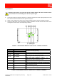
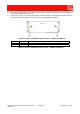
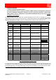
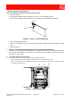
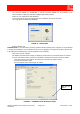
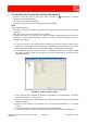
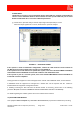
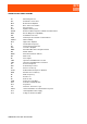
Table Of Contents
- 1800MHz-1900MHz ADJUSTABLE BANDWIDTH OFF-AIR REPEATERS_91 080 0701F
- INDEX
- 1) SAFETY RULES
- 2) STANDARDS
- 3) GENERAL DESCRIPTION
- 3.1) EXAMPLE: USE IN TUNNELS
- 3.2) OPERATING PRINCIPLE - 1800MHz ADJUSTABLE BANDWIDTH OFF-AIR REPEATERS
- 3.3) ATTACHED DOCUMENTS
- TECHNICAL CHARACTERISTICS 1800MHZ
- ILLUSTRATIVE 1 - Equipment composition and backplane access points map
- ILLUSTRATIVE 2 - Modules access points map and external access points map
- TECHNICAL CHARACTERISTICS 1900MHz
- ILLUSTRATIVE 1 - Equipment composition and backplane access points map
- ILLUSTRATIVE 2 - Modules access points map and external access points map
- 4) INSTALLATION AND POWER-UP PROCEDURES
- ABBREVIATIONS AND ACRONYMS
- INDEX

1800MHz-1900MHz Off-Air Repeaters (OR Series) Page 91 080 0701F – Rel.04
CHAPTER 4
4.9
b. Models equipped with GSM modem
How to install/remove the SIM card from the built-in modem
• Open the repeater.
• Check that the switches inside the repeater are set to 0 - OFF (FIGURE 1a and b).
• Insert the SIM enabled to data transmission in not transparent mode 9600BPS (FIGURE 6)
FIGURE 6 – DETAIL OF THE SIM INSERTION
• Close the Management Module
• Switch on the equipment (AC voltage circuit breaker, ref. 57, 48Vdc circuit breaker, ref. 22, FIGURE
1a-b).
• Close the repeater.
7. INSTALL THE OPERATION AND MAINTENANCE SOFTWARE OMT REPEATER
Install on your PC the Operation and Maintenance Terminal software to set and manage the equipment
(please refer to the software User’s manual). The repeater can be managed in remote mode via a built-
in modem, or in local mode.
8. START OMT Repeater IN LOCAL MODE
In LOCAL mode the notebook is connected to the repeater via RS232 serial cable.
- Open the repeater door (by unscrewing four screws located on the equipment front door).
Connect your notebook to the management module (connector RS232, ref. 34, FIGURE 7) using the provided
serial cable (null-modem type).
P
HIGH POWER AMPLIFIER
IN
SPV BUS
OUT
UP LINK
132KHz
ALARM
+5V
RL
OPERATING
U
ULNA
HPA D
D
BS 1
BS 2
HIGH POWER AMPLIFIER
SPV BUS
DOWN LINK
P
IN
OUT
In
Out
Out
In
BAND-SELECTIVE 1
In
OutIn
Out
DOWN-LINK
UP-LINK
DOWN-LINK
UP-LINK
BAND-SELECTIVE 2
POWER SUPPLY
5V5 10V5
LNA DOWN
LNA UP
RS232 (Repeate r) RS232 (Modem)
RS232
Modem
ref. 58
RS232
Link
ref. 59
RS232
Repeater
ref. 34
FIGURE 7 – RS232 CONNECTORS