
User's Manual
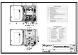
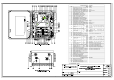

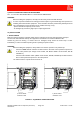
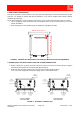
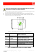
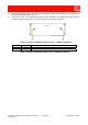
Table Of Contents
- 1800MHz-1900MHz ADJUSTABLE BANDWIDTH OFF-AIR REPEATERS_91 080 0701F
- INDEX
- 1) SAFETY RULES
- 2) STANDARDS
- 3) GENERAL DESCRIPTION
- 3.1) EXAMPLE: USE IN TUNNELS
- 3.2) OPERATING PRINCIPLE - 1800MHz ADJUSTABLE BANDWIDTH OFF-AIR REPEATERS
- 3.3) ATTACHED DOCUMENTS
- TECHNICAL CHARACTERISTICS 1800MHZ
- ILLUSTRATIVE 1 - Equipment composition and backplane access points map
- ILLUSTRATIVE 2 - Modules access points map and external access points map
- TECHNICAL CHARACTERISTICS 1900MHz
- ILLUSTRATIVE 1 - Equipment composition and backplane access points map
- ILLUSTRATIVE 2 - Modules access points map and external access points map
- 4) INSTALLATION AND POWER-UP PROCEDURES
- ABBREVIATIONS AND ACRONYMS
- INDEX

1800MHz-1900MHz Off-Air Repeaters (OR Series) Page 91 080 0701F – Rel.04
CHAPTER 4
4.1
4) INSTALLATION AND POWER-UP PROCEDURES
Ref.: ILL DCS OFF-AIR REPEATERS / ILL PCS OFF-AIR REPEATERS
WARNING:
Before installing the equipment, carefully read the safety norms herewith attached.
A correct repeater installation and setting procedure requires a good knowledge and experience in
installing telecommunication equipment. These activities should be performed by skilled personnel
only. Remember that if the equipment is not installed correctly, it may:
- put the donor BTS temporary out of service,
- be damaged by excessively high input or output signal levels.
4.1) INSTALLATION
1. INITIAL CHECK
Make sure that the supply is complete and/or that the material has not been damaged during transport.
The list of the materials that make up the equipment is described in the relative PACKING LIST.
Should any parts be missing, or should some be damaged, kindly inform the Sales Dept. of RFS
immediately, in order to facilitate replacing and/or repairing the parts involved.
WARNING:
Before installing the equipment, always make sure that the repeater is not powered up:
- Check that both ON/OFF switches located inside the alternate current powered repeater are
in the OFF position (AC voltage circuit breaker, ref. 59 and 48Vdc circuit breaker, ref. 22
FIGURE 1a).
- Check that the ON/OFF switch (48Vdc circuit breaker, ref. 22, FIGURE 1b) located inside the
direct current powered repeater is in the OFF position.
The LEDs inside the repeater must be turned off.
FIGURE 1 – EQUIPMENT POWER SWITCHES
AC voltage
circuit breaker
ref. 59
a) 230Vac MODEL
INTERNAL VIEW
b) 48Vdc MODEL
INTERNAL VIEW
48Vdc circuit
breaker
ref. 22
P
HIGH POWER AMPLIFIER
IN
SPV BUS
OUT
UP LINK
132KHz
ALARM
+5V
RL
OPERATING
U
ULNA
HPA D
D
BS 1
BS 2
HIGH POWER AMPLIFIER
SPV BUS
DOWN LINK
P
IN
OUT
In
Out
Out
In
BAND-SELECTIVE 1
In
Out
In
Out
DOWN-LINK
UP-LINK
DOWN-LINK
UP-LINK
BAND-SELECTIVE 2
1710-1785MHz1805-1880MHz
1710-1785MHz 1805-1880MHz
POWER SUPPLY
5V5 10V5
LNA DOWN
LNA UP
P
HIGH POWER AMPLIFIER
IN
SPV BUS
OUT
UP LINK
132KHz
ALARM
+5V
RL
OPERATING
U
ULNA
HPA D
D
BS 1
BS 2
HIGH POWER AMPLIFIER
SPV BUS
DOWN LINK
P
IN
OUT
In
Out
Out
In
BAND-SELECTIVE 1
In
Out
In
Out
DOWN-LINK
UP-LINK
DOWN-LINK
UP-LINK
BAND-SELECTIVE 2
1710-1785MHz1805-1880MHz
1710-1785MHz 1805-1880MHz
POWER SUPPLY
5V5 10V5
LNA DOWN
LNA UP
0
48Vdc circuit
breaker
ref. 22