
User's Manual
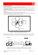
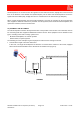
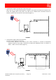
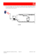
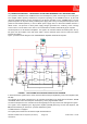
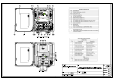

Table Of Contents
- 1800MHz-1900MHz ADJUSTABLE BANDWIDTH OFF-AIR REPEATERS_91 080 0701F
- INDEX
- 1) SAFETY RULES
- 2) STANDARDS
- 3) GENERAL DESCRIPTION
- 3.1) EXAMPLE: USE IN TUNNELS
- 3.2) OPERATING PRINCIPLE - 1800MHz ADJUSTABLE BANDWIDTH OFF-AIR REPEATERS
- 3.3) ATTACHED DOCUMENTS
- TECHNICAL CHARACTERISTICS 1800MHZ
- ILLUSTRATIVE 1 - Equipment composition and backplane access points map
- ILLUSTRATIVE 2 - Modules access points map and external access points map
- TECHNICAL CHARACTERISTICS 1900MHz
- ILLUSTRATIVE 1 - Equipment composition and backplane access points map
- ILLUSTRATIVE 2 - Modules access points map and external access points map
- 4) INSTALLATION AND POWER-UP PROCEDURES
- ABBREVIATIONS AND ACRONYMS
- INDEX

MODULES ACCESS POINTS MAP
Ref. DESCRIPTION
1 DUPLEXER - BTS side - Up Link path SMA connector
2 LNA - Down Link - input
3 Band Selective 2 Up-Link path output
4 DUPLEXER - BTS side - input/output SMA connector
5 Directional coupler - BTS side - SMA (f) input/output connector
6 DUPLEXER - BTS side - SMA Down Link connector
9 LNA - Up Link path - output
10 Band Selective 1 Up Link Input
11 Band Selective 1 Down Link Output
12 Band Selective 2 Down Link Input
13 LNA - Down Link path - output
14 LNA - Up Link path - input
15 Band Selective 2 Up Link path input
16 Band Selective 2 Down Link path output
17 Band Selective 1 Down Link path Input
18 Band Selective 1 Up Link path output
21 DUPLEXER - MS side - Up Link path SMA connector
22 48Vdc ONLY circuit breaker
23 DUPLEXER - MS side - input/output SMA connector
24 Directional coupler - MS side - SMA (f) input/output connector
25 DUPLEXER - MS side - Down Link path SMA connector
26 GREEN LED: +5Vdc available
GREEN
HPA - UP LINK - communicates with management
unit
27
GREEN / RED LED
HPA UP
RED
HPA - UP LINK - does not communicate with
management unit
28 GREEN LED: +10.5V available
GREEN
HPA - DOWN LINK - communicates with
management unit
29
GREEN / RED LED
HPA DOWN
RED
HPA - DOWN LINK - does not communicate with
management unit
30 HPA Down Link output
31 Sub-D 15-pole management link between Down Link HPA and management unit
32 HPA Down Link input
33 HPA Down Link monitoring SMA connector
34 Sub-D 9-poles RS232 connector
GREEN
LNA - DOWN LINK - communicates with
management unit
35
GREEN / RED LED
LNA DOWN
RED
LNA - DOWN - does not communicate with
management unit
GREEN
LNA - UP LINK - communicates with management
unit
36
GREEN / RED LED
LNA UP
RED
LNA - UP LINK - does not communicate with
management unit
GREEN BS1 communicates with management unit
37
GREEN / RED LED
Band Selective 1
RED BS1 does not communicate with management unit
38 Sub-D 15-pole management link between Down Link HPA and management unit
GREEN BS2 communicates with management unit
39
GREEN / RED LED
Band Selective 2
RED BS2 does not communicate with management unit
40 GREEN LED 132kHz: 132kHz (line amplifier management carrier) correctly operating
41 RED LED: Return Loss alarm
42 Sub-D 15-pole management link between Up Link HPA and management unit
43 Sub-D 15-pole management link between Up Link HPA and management unit
44 HPA Up Link input
45 HPA Up Link monitoring SMA connector
46 GSM modem RF output
47 HPA Up Link output
RED ON Trying to connect to network
48
RED LED: modem
operation
BLINKING
RED
Modem correctly operating
49 GREEN LED: equipment correctly operating
50 GREEN LED: 5.5V available
51 RED LED: equipment fault
57 (*) AC voltage ONLY circuit breaker
EXTERNAL ACCESS POINTS MAP
52 BTS side 7/16 RF connector
53 Equipment Grounding
54 (*) AC voltage input (230Vac)
55 48Vdc input / external alarms Connector
56 MS side 7/16 RF connector
(*) 230VAC MODEL ONLY
P
HIGH POWER AMPLIFIER
IN
SPV BUS
OUT
UP LINK
LNA DOWN
132KHz
ALARM
+5V
RL
OPERATING
U
U LNA
HPA D
D
BS 1
BS 2
RS232
HIGH POWER AMPLIFIER
SPV BUS
DOWN LINK
P
IN
OUT
LNA UP
In
Out
Out
In
BAND-SELECTIVE 1
In
OutIn
Out
DOWN-LINK
UP-LINK
DOWN-LINK
UP-LINK
BAND-SELECTIVE 2
1
45 44 43 42 40 39 33 32 30
4 6 9 10 14 15
23
2111 16 18172 13
52
47
34 3136
29
49
37
223 12
1710-1785MHz
1710-1785MHz
1805-1880MHz
1805-1880MHz
26
38
INTERNAL VIEW - MODULES ACCESS POINTS
BOTTOM VIEW - REPEATER CASE CLOSED
EXTERNAL ACCESS POINTS
POWER SUPPLY
5V5
10V5
50
28
27
51
41 35
25
24
5
46
48
55 56
Copyright protection according to law
ILL DCS OFF-AIR REPEATERS
Scale
Revisions
Title
2/2
Sheet
Date
Part Number
1800MHz ADJUSTABLE BAND OFF-AIR REPEATERS
MODULES ACCESS POINTS MAP AND EXTERNAL
ACCESS POINTS MAP
Drawn by
CG
AV
MN
Approved by
Checked by
57
0
ED. 02
31/01/2007
ED. 01-1
29/09/2006
53 54