
User's Manual
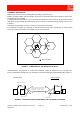
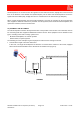
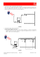
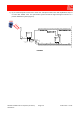
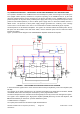
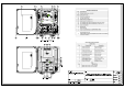

Table Of Contents
- 1800MHz-1900MHz ADJUSTABLE BANDWIDTH OFF-AIR REPEATERS_91 080 0701F
- INDEX
- 1) SAFETY RULES
- 2) STANDARDS
- 3) GENERAL DESCRIPTION
- 3.1) EXAMPLE: USE IN TUNNELS
- 3.2) OPERATING PRINCIPLE - 1800MHz ADJUSTABLE BANDWIDTH OFF-AIR REPEATERS
- 3.3) ATTACHED DOCUMENTS
- TECHNICAL CHARACTERISTICS 1800MHZ
- ILLUSTRATIVE 1 - Equipment composition and backplane access points map
- ILLUSTRATIVE 2 - Modules access points map and external access points map
- TECHNICAL CHARACTERISTICS 1900MHz
- ILLUSTRATIVE 1 - Equipment composition and backplane access points map
- ILLUSTRATIVE 2 - Modules access points map and external access points map
- 4) INSTALLATION AND POWER-UP PROCEDURES
- ABBREVIATIONS AND ACRONYMS
- INDEX

1800MHz-1900MHz Off-Air Repeaters (OR Series) Page 91 080 0701F – Rel.04
CHAPTER 3
3.3
• Tunnels with a length in the 300-meter to 600-meter range.
Also in this case, one single Off-Air Repeater is sufficient. The repeater is located at the entrance to the
tunnel and equipped with a leaky cable. This cable can be combined with a directional antenna to
irradiate a portion of the area in front of the tunnel exit (Figure 4).
FIGURE 4
• Tunnels with a length of more than 600 meters.
The signal can be enhanced in two ways:
a) By an Off-Air Repeater at the entrance to the tunnel, connected to a cascade of bi-directional
amplifiers inside the tunnel which re-generate the signal with amplification steps at a distance of
250mt. ÷ 400mt. from one another (Figure 5).
FIGURE 5
DOWN
UP
DO
W
N
L
I
N
K
U
P
L
I
N
K
Power Supply
(230Vac)
OFF-AIR
REPEATER
UP
DOWN
48Vdc Power Supply
and external signals
POWER
SUPPLY
DC
DC
BF
RF
BF
RF-DC-BF
RF
UP
DOWN
DOWN
UP
AMPLIFICATION STEP
RF-DC-BF
BI-DIRECTIONAL
AMPLIFIER
RF-DC-BF
RF-DC-BF
RF-DC-BF
D
O
WN
L
I
N
K
U
P
L
I
N
K
BI-DIRECTIONAL
AMPLIFIER
Bias-T
OFF-AIR
REPEATER