
User's Manual
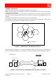
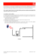
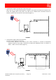
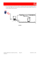
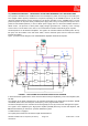
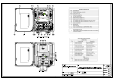

Table Of Contents
- 1800MHz-1900MHz ADJUSTABLE BANDWIDTH OFF-AIR REPEATERS_91 080 0701F
- INDEX
- 1) SAFETY RULES
- 2) STANDARDS
- 3) GENERAL DESCRIPTION
- 3.1) EXAMPLE: USE IN TUNNELS
- 3.2) OPERATING PRINCIPLE - 1800MHz ADJUSTABLE BANDWIDTH OFF-AIR REPEATERS
- 3.3) ATTACHED DOCUMENTS
- TECHNICAL CHARACTERISTICS 1800MHZ
- ILLUSTRATIVE 1 - Equipment composition and backplane access points map
- ILLUSTRATIVE 2 - Modules access points map and external access points map
- TECHNICAL CHARACTERISTICS 1900MHz
- ILLUSTRATIVE 1 - Equipment composition and backplane access points map
- ILLUSTRATIVE 2 - Modules access points map and external access points map
- 4) INSTALLATION AND POWER-UP PROCEDURES
- ABBREVIATIONS AND ACRONYMS
- INDEX

1800MHz-1900MHz Off-Air Repeaters (OR Series) Page 91 080 0701F – Rel.04
CHAPTER 3
3.2
Off-Air Repeaters on one side receive the signals from the radio base station, amplify them and re-transmit
them in the direction of the shadow area (down-link path). On the other side Off-Air Repeaters receive the
signals from the mobiles (MS), amplify them and re- transmit them to the base station (up-link path).
When a single Off-Air Repeater does not provide satisfactory coverage, the repeater can be used along with
other equipment. Different solutions are provided: cascade systems, based on Bi-Directional Amplifiers, and
optical fibre solutions, based on Remote Units.
3.1) EXAMPLE: USE IN TUNNELS
The Off-Air Repeater interfaces directly with the BTS of the provider of the services to be extended, and can
be used along with other equipment distributed inside the tunnels. Such equipment can be divided into two
types, according to the radio-coverage system used:
- Bi-directional amplifiers, for cascade systems.
- Remote Units, for optical systems.
The following are a few examples of general projects for radio-electric coverage in tunnels.
• Tunnels with a length of less than 300 meters.
In this case, one single Off-Air Repeater is sufficient. It is located at the entrance to the tunnel, equipped
with an antenna which irradiates in the direction of the shadow zone (Figure 3).
FIGURE 3
DOWN
UP
DO
W
N
L
I
N
K
U
P
L
I
N
K
Power Supply
(230Vac)
OFF-AIR
REPEATER
UP
DOWN
48Vdc Power Supply
and external signals