
User's Manual
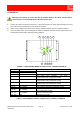
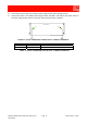
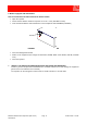
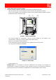
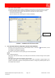
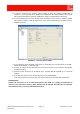
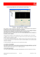
Table Of Contents
- 900MHz ADJUSTABLE BANDWIDTH OFF-AIR REPEATERS_91 080 0716F
- INDEX
- 1) SAFETY RULES
- 2) STANDARDS
- 3) GENERAL DESCRIPTION
- 3.1) EXAMPLE: USE IN TUNNELS
- 3.2) OPERATING PRINCIPLE - 800MHz/900MHz ADJUSTABLE BANDWIDTH OFF-AIR REPEATERS
- 3.3) ATTACHED DOCUMENTS
- SMR - TECHNICAL CHARACTERISTICS
- CDMA/TDMA/AMPS - TECHNICAL CHARACTERISTICS
- EGSM - TECHNICAL CHARACTERISTICS
- GSM-R - TECHNICAL CHARACTERISTICS
- CDMA/TDMA/AMPS - ILLUSTRATIVE 1 - Equipment composition and backplane access points map
- CDMA/TDMA/AMPS - ILLUSTRATIVE 2 - Modules access points map and external access points map
- EGSM - ILLUSTRATIVE 1 - Equipment composition and backplane access points map
- EGSM - ILLUSTRATIVE 2 - Modules access points map and external access points map
- GSM-R - ILLUSTRATIVE 1 - Equipment composition and backplane access points map
- GSM-R - ILLUSTRATIVE 2 - Modules access points map and external access points map
- 4) INSTALLATION AND POWER-UP PROCEDURES
- ABBREVIATIONS AND ACRONYMS
- INDEX

800MHz-900MHz Off-Air Repeaters (OR Series) Page 91 080 0716F – Rel.06
CHAPTER 4
13
g) Check via the spectrum analyzer that the output signal level (MS side) is correct.
When the output signal level is correct, disconnect the spectrum analyzer.
FIGURE 11 – ‘SPECTRUM’ PANEL - EXAMPLE
If the repeater is used in stand-alone configuration, connect the cable from the service antenna to
the MS connector on the bottom of the repeater (ref. 56, FIGURE 3).
If the repeater is the head station of an optical fiber system, refer to the OPTICAL FIBER COVERAGE
SOLUTIONS technical handbook to install and set Master Unit and Remote Units.
If the repeater is part of a cascade system, refer to the IN-LINE AMPLIFIERS technical handbook to
install and set in-line amplifiers.
During operation the equipment can be managed, both in LOCAL and in REMOTE mode, via the software.
In REMOTE mode the equipment is managed via a modem link. On the repeater side the modem is installed
within the equipment management module.
In case of repeater equipped with GSM modem, if installing /removing the SIM card from the built-in modem
is necessary, please refer to the for procedure 6b (HOW TO INSTALL/REMOVE THE SIM CARD FROM
THE BUILT-IN MODEM).
For details regarding the software, please refer to the software User’s manual.
4.3) CLOSING THE EQUIPMENT
The repeater front door has to be closed carefully to guarantee protection of the equipment (i.e. to prevent
dust and water getting inside the box). All the screws located on the equipment front door have to be
appropriately tightened. We suggest you use an X tightening sequence
4.4) ROUTINE MAINTENANCE
This equipment does not require any ORDINARY MAINTENANCE (or preventive maintenance) servicing.