
User's Manual
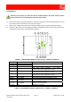
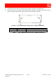
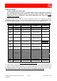
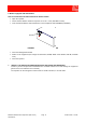
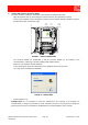
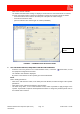
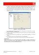
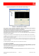
Table Of Contents
- 900MHz ADJUSTABLE BANDWIDTH OFF-AIR REPEATERS_91 080 0716F
- INDEX
- 1) SAFETY RULES
- 2) STANDARDS
- 3) GENERAL DESCRIPTION
- 3.1) EXAMPLE: USE IN TUNNELS
- 3.2) OPERATING PRINCIPLE - 800MHz/900MHz ADJUSTABLE BANDWIDTH OFF-AIR REPEATERS
- 3.3) ATTACHED DOCUMENTS
- SMR - TECHNICAL CHARACTERISTICS
- CDMA/TDMA/AMPS - TECHNICAL CHARACTERISTICS
- EGSM - TECHNICAL CHARACTERISTICS
- GSM-R - TECHNICAL CHARACTERISTICS
- CDMA/TDMA/AMPS - ILLUSTRATIVE 1 - Equipment composition and backplane access points map
- CDMA/TDMA/AMPS - ILLUSTRATIVE 2 - Modules access points map and external access points map
- EGSM - ILLUSTRATIVE 1 - Equipment composition and backplane access points map
- EGSM - ILLUSTRATIVE 2 - Modules access points map and external access points map
- GSM-R - ILLUSTRATIVE 1 - Equipment composition and backplane access points map
- GSM-R - ILLUSTRATIVE 2 - Modules access points map and external access points map
- 4) INSTALLATION AND POWER-UP PROCEDURES
- ABBREVIATIONS AND ACRONYMS
- INDEX

800MHz-900MHz Off-Air Repeaters (OR Series) Page 91 080 0716F – Rel.06
CHAPTER 4
5
4.2) POWER-UP
Warning: before power up, make sure that the isolation between the donor antenna and the
service antenna is at least 15dB greater than the repeater gain.
1. Connect the cable from the donor antenna to a spectrum analyzer and check input signal presence and
level. After measurement disconnect the spectrum analyzer.
2. Switch on the equipment by means of the switches placed inside the repeater (FIGURE 1a and b).
3. Check the LEDs status on the management module: FIGURE 4 and Table 3 show LEDs status on the
management module under normal operating conditions.
FIGURE 4 – MANAGEMENT MODULE: LEDS STATUS - CORRECT POWER UP
REF. STATUS MEANING
LED 1S OFF
LED 2S ON
Equipment correctly operating
LED 3S ON Management module: +5Vdc available
LED 4S ON, GREEN
HPA (High Power Amplifier) - UP LINK -
communicates with management module
LED 5S ON, GREEN
HPA (High Power Amplifier) - DOWN LINK -
communicates with management module
LED 6S ON, GREEN
LNA (Low Noise Amplifier) - DOWN LINK -
communicates with management module
LED 7S ON, GREEN BS1 communicates with management module
LED 8S ON, GREEN BS2 communicates with management module
LED 9S ON, GREEN
LNA (Low Noise Amplifier) - UP LINK - communicates
with management module
LED 10S ON, GREEN 132kHz correctly operating
LED 11S OFF
NO Return Loss alarm
TABLE 3 - MANAGEMENT MODULE: LEDS STATUS - CORRECT POWER UP
2S1S 4S3S 5S
11S
OPERATING
+5V
ALARM
RL
132KHz
HPAU D
LNA
BS 2
BS 1
U D
9S10S 8S 7S 6S