
User's Manual
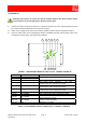
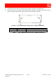
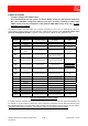
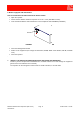
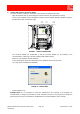
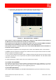
Table Of Contents
- 900MHz ADJUSTABLE BANDWIDTH OFF-AIR REPEATERS_91 080 0716F
- INDEX
- 1) SAFETY RULES
- 2) STANDARDS
- 3) GENERAL DESCRIPTION
- 3.1) EXAMPLE: USE IN TUNNELS
- 3.2) OPERATING PRINCIPLE - 800MHz/900MHz ADJUSTABLE BANDWIDTH OFF-AIR REPEATERS
- 3.3) ATTACHED DOCUMENTS
- SMR - TECHNICAL CHARACTERISTICS
- CDMA/TDMA/AMPS - TECHNICAL CHARACTERISTICS
- EGSM - TECHNICAL CHARACTERISTICS
- GSM-R - TECHNICAL CHARACTERISTICS
- CDMA/TDMA/AMPS - ILLUSTRATIVE 1 - Equipment composition and backplane access points map
- CDMA/TDMA/AMPS - ILLUSTRATIVE 2 - Modules access points map and external access points map
- EGSM - ILLUSTRATIVE 1 - Equipment composition and backplane access points map
- EGSM - ILLUSTRATIVE 2 - Modules access points map and external access points map
- GSM-R - ILLUSTRATIVE 1 - Equipment composition and backplane access points map
- GSM-R - ILLUSTRATIVE 2 - Modules access points map and external access points map
- 4) INSTALLATION AND POWER-UP PROCEDURES
- ABBREVIATIONS AND ACRONYMS
- INDEX

800MHz-900MHz Off-Air Repeaters (OR Series) Page 91 080 0716F – Rel.06
CHAPTER 4
4
• AC POWERED EQUIPMENT (ALTERNATE CURRENT)
- Connect the 230Vac power cable to the connector located on the bottom of the repeater (ref. 54,
FIGURE 3). The connector pin assignments are detailed in Table 2.
230Vac POWER SUPPLY CONNECTOR
PIN CABLE 230VAC POWER SUPPLY
CABLE COLOR
1 LINE BROWN
2 NEUTRAL BLUE
3 GROUND (GND) YELLOW / GREEN
4 NOT CONNECTED
TABLE 2 – 230Vac POWER SUPPLY CONNECTOR PIN-OUT
- Connect the other end of the cable to the power supply source (230Vac).
- Also connect the 48Vdc power and alarms cable, provided standard, to the 15-pin connector located on
the bottom of the equipment (ref. 55, FIGURE 3).
The cable makes remote signals available. The connector pin-out is detailed into table 1.
The cable can also be connected to a 48Vdc power supply, to feed the equipment with a D.C. voltage.
PLEASE NOTE:
The 48Vdc power supply cable (also including the external alarms), provided standard with the
equipment, must never be longer than 3 meters in length (connectors included).