
User's Manual
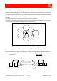
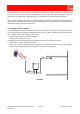
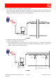
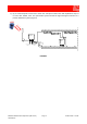
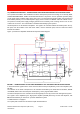

Table Of Contents
- 900MHz ADJUSTABLE BANDWIDTH OFF-AIR REPEATERS_91 080 0716F
- INDEX
- 1) SAFETY RULES
- 2) STANDARDS
- 3) GENERAL DESCRIPTION
- 3.1) EXAMPLE: USE IN TUNNELS
- 3.2) OPERATING PRINCIPLE - 800MHz/900MHz ADJUSTABLE BANDWIDTH OFF-AIR REPEATERS
- 3.3) ATTACHED DOCUMENTS
- SMR - TECHNICAL CHARACTERISTICS
- CDMA/TDMA/AMPS - TECHNICAL CHARACTERISTICS
- EGSM - TECHNICAL CHARACTERISTICS
- GSM-R - TECHNICAL CHARACTERISTICS
- CDMA/TDMA/AMPS - ILLUSTRATIVE 1 - Equipment composition and backplane access points map
- CDMA/TDMA/AMPS - ILLUSTRATIVE 2 - Modules access points map and external access points map
- EGSM - ILLUSTRATIVE 1 - Equipment composition and backplane access points map
- EGSM - ILLUSTRATIVE 2 - Modules access points map and external access points map
- GSM-R - ILLUSTRATIVE 1 - Equipment composition and backplane access points map
- GSM-R - ILLUSTRATIVE 2 - Modules access points map and external access points map
- 4) INSTALLATION AND POWER-UP PROCEDURES
- ABBREVIATIONS AND ACRONYMS
- INDEX

800MHz-900MHz Off-Air Repeaters (OR Series) Page 91 080 0716F – Rel.06
CHAPTER 3
5
3.2) OPERATING PRINCIPLE – 800MHz/900MHz ADJUSTABLE BANDWIDTH OFF-AIR REPEATERS
The repeaters described in this handbook have been developed to permit cell coverage as set forth by SMR,
CDMA/GSM/TDMA/AMPS, GSM-R and EGSM standards for cell phones. The DC powered repeaters (OR1)
can be power-fed by a 48Vdc power supply source only. The AC powered repeaters (OR2) can be power-fed
from MAINS (230Vac) or from a 48Vdc power supply source or both from MAINS and from a 48Vdc source.
The presence of both power supply voltages guarantees the continuity of the coverage service even in case
of failure of one source. The commutation is handled automatically by the repeater.
Off-Air Repeaters are bi-directional amplifiers. The signal to be extended follows two distinct paths: the up-
link path, from the mobiles to the radio base station, and the down-link path, from the radio base station
towards the mobiles.
Figure 7 provides the adjustable band Off-Air Repeaters block-diagram.
FIGURE 7 – 800MHz/900MHz ADJUSTABLE BANDWIDTH OFF-AIR REPEATERS BLOCK-DIAGRAM
In down-link the RF signal from the donor antenna is filtered and pre-amplified by a low-noise amplifier (LNA,
ref. C1).
The selection of the band of frequencies to be extended is handled by two band-selective modules, ref. D1
and ref. D2, which make the band-pass and frequency center programmable entities.
The band of frequencies to be extended can be managed by the user by means of the management system.
The signal is then amplified by the High power amplifier (ref. E1) filtered by the MS side duplexer, ref.
B2,and transmitted by an antenna or a passive distribution system.
A VSWR detector is equipped.
The up-link path is identical to the down-link path described above.
BTS
dB
ALC
dB
ALC
MS
DOWN
UP
DOWN
UP
MANAGEMENT BUS
MANAGEMENT
UNIT
MODEM
NETWORK
RS232
DC/DC
CONVERTER
LNA DOWN
HPA
DOWN
LNA UP
HPA UP
BAND SELECTIVE 1
UP LINK
DOWN LINK
BAND SELECTIVE 2
UP LINK
DOWN LINK
5.5Vdc
48Vdc
48Vdc
IN
AC/DC
CONVERTER
230Vac
IN
5.5Vdc
10.5Vdc
10.5Vdc
5.5Vdc
10.5Vdc
5.5Vdc
10.5Vdc
5.5Vdc
5.5Vdc
5.5Vdc
10.5Vdc
5.5Vdc
A1
B1
C1 D1
E1
B2
C2
E2
A2
D2
LF
G