
Handbook
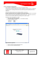
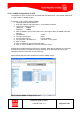
Table Of Contents
- 1 Introduction
- 2 ClearFill®Star System Description
- 3 System Design Guidelines
- 3.1 CDMA Basics (in preparation)
- 3.2 Required information for system design
- 3.3 Design step by step
- 3.4 Estimated RF Coverage per RRH
- 3.5 Right-sizing - the beacon feature (in preparation)
- 3.6 Capacity demand - number for BSIs (in preparation)
- 3.7 System Architecture
- 4 System Installation
- 4.1 General
- 4.2 System Installation (Hardware Installation)
- 4.3 Installation Radio Remote Head (RRH)
- 4.4 Installation Gigabit Ethernet Switch (GES)
- 4.5 Installation Base Station Interface (BSI)
- 4.6 Installation NMS Server (Hardware)
- 4.7 Commissioning of NMS
- 5 NMS Overview
- 5.1 Introduction
- 5.2 Starting the NMS
- 5.3 Tools and Utilities of NMS server
- 5.4 Main Window of NMS Application Client (structure)
- 5.5 The NMS client functionality
- 5.6 Right Click Menus
- 5.7 RRH Configuration
- 5.8 BSI Configuration
- 6 Configuration Management
- 7 System Supervision
- 8 Remote Management and Supervision
- 9 Operational used cases/Maintenance
- 10 System Specifications and Technical Data
- 11 Conformance Statements
- 11.1 United States
- 11.1.1 Introduction
- 11.1.2 Federal Communications Commission (FCC)
- 11.1.3 FCC Part 15 Class A
- 11.1.4 RF approval
- 11.1.5 IEC product safety conformance
- 11.1.6 Indoor applications
- 11.1.7 Antenna exposure
- 11.1.8 Radiofrequency radiation exposure Information
- 11.1.9 Packaging collection and recovery requirements
- 11.1.10 Recycling / take-back / disposal of products and batteries
- 11.2 Canada
- 11.1 United States
- 12 Appendix

ClearFill Star CDMA
1100187 Rev. 1.0
Page 55 of 152
4.3 Installation Radio Remote Head (RRH)
Before beginning the installation of the RRH, all RF cables (if applicable) and Ethernet cables
should be installed.
Please follow the general procedure for installing the RRH as it is
described below. It is important that the above installation instructions are
followed in the sequence presented to ensure a correct and save
installation.
1. Transport the RRH to the installation site in its packaging.
2. Remove the RRH from its packaging and check for obvious signs of physical
damage. If unit is physically damaged do not proceed with the installation.
3. Check the packing for completeness according to the packing list.
4. Take the metallic holder for the RRH and us it as a template to mark the three
drilling holes at the designated mounting place.
5. The provided dowels in the accessories kit are suitable for installation in indoor
areas (closed spaces) only and for following wall constructions:
- Concrete
- Pre-stressed hollow-core concrete slabs
- Natural stone with dense structure
- Solid brick
- Sand-lime solid brick
- Solid block made from lightweight concrete
- Air Crete
- Solid panel made from gypsum
- Hollow block made from lightweight concrete
- Slabs made of perforated bricks
- Hollow concrete blocks etc.
In case the provided dowels do not fit, special fixing material has to be used. It has
to be ensured that the wall fixings are adequate for a total weight of more than 1.4
lbs (600 g).
6. Drill the holes to which the holder is to be fitted.
7. If the afore mentioned wall/roof construction is given, mount the holder with
appropriate dowels/screws to its place and mount the RRH onto the holder by
sliding it onto the holder. Check the firm fastening.
8. Connect the antenna or a DAS to the output port of the RRH. The connection cable
between RRH and antenna has to be < 3 m (< 10 ft). The orientation of the antenna
shall be vertical.
9. To complete the installation, connect the LAN cable to the RJ45-port of the RRH.
10. For rack-mount or desk-mount installations of the RRH, use the self-adhesive rubber
bumpers.