
Handbook
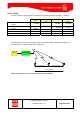
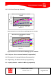
Table Of Contents
- 1 Introduction
- 2 ClearFill®Star System Description
- 3 System Design Guidelines
- 3.1 CDMA Basics (in preparation)
- 3.2 Required information for system design
- 3.3 Design step by step
- 3.4 Estimated RF Coverage per RRH
- 3.5 Right-sizing - the beacon feature (in preparation)
- 3.6 Capacity demand - number for BSIs (in preparation)
- 3.7 System Architecture
- 4 System Installation
- 4.1 General
- 4.2 System Installation (Hardware Installation)
- 4.3 Installation Radio Remote Head (RRH)
- 4.4 Installation Gigabit Ethernet Switch (GES)
- 4.5 Installation Base Station Interface (BSI)
- 4.6 Installation NMS Server (Hardware)
- 4.7 Commissioning of NMS
- 5 NMS Overview
- 5.1 Introduction
- 5.2 Starting the NMS
- 5.3 Tools and Utilities of NMS server
- 5.4 Main Window of NMS Application Client (structure)
- 5.5 The NMS client functionality
- 5.6 Right Click Menus
- 5.7 RRH Configuration
- 5.8 BSI Configuration
- 6 Configuration Management
- 7 System Supervision
- 8 Remote Management and Supervision
- 9 Operational used cases/Maintenance
- 10 System Specifications and Technical Data
- 11 Conformance Statements
- 11.1 United States
- 11.1.1 Introduction
- 11.1.2 Federal Communications Commission (FCC)
- 11.1.3 FCC Part 15 Class A
- 11.1.4 RF approval
- 11.1.5 IEC product safety conformance
- 11.1.6 Indoor applications
- 11.1.7 Antenna exposure
- 11.1.8 Radiofrequency radiation exposure Information
- 11.1.9 Packaging collection and recovery requirements
- 11.1.10 Recycling / take-back / disposal of products and batteries
- 11.2 Canada
- 11.1 United States
- 12 Appendix

ClearFill Star CDMA
1100187 Rev. 1.0
Page 49 of 152
3.7 System Architecture
3.7.1 Rules from the Ethernet World
3.7.1.1 CAT5 lengths
Maximum CAT5 (or higher) cable length is 100 m (300 ft).
3.7.1.2 Optical lengths
Maximum length of the multi mode fibers is 550 m (1650 ft)
3.7.1.3 Cascade
Rules:
Up to 4 Levels, including the main switch connected to the BSI.
It is mandatory that all RRHs have same number of switches on the signal path to the
BSI. This is applicable for each VLAN.
Per switch a RRH is automatically assigned for the summing of up to 8 RRHs.
The maximum number of RRH (summing or not), connected to one GES is limited to
8. For higher numbers, PoE limitations may apply.
The total number of RRH per BSI is limited to 16.
3.7.2 Gigabit Ethernet Switch
3.7.2.1 Layer
Layer 2 in the physical layer model
3.7.2.2 Cascade
Rules:
Up to 4 Levels, including the main switch connected to the BSI.
It is mandatory that all RRHs have same number of switches on the signal path to the
BSI. This is applicable for each VLAN.
Per switch a RRH is assigned for the summing of up to 8 RRHs. In case more than 8
are connected to an individual switch there will be 2 RRHs dedicated for the
summing.
This should be avoided for the time being. Typical use case is 2 VLANs on the switch
(not more than 8 RRHs per VLAN per Switch).
The maximum number of RRH (summing or not), connected to one BSI is limited to 8.