
Handbook
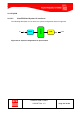
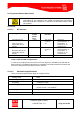
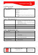
Table Of Contents
- 1 Introduction
- 2 ClearFill®Star System Description
- 3 System Design Guidelines
- 3.1 CDMA Basics (in preparation)
- 3.2 Required information for system design
- 3.3 Design step by step
- 3.4 Estimated RF Coverage per RRH
- 3.5 Right-sizing - the beacon feature (in preparation)
- 3.6 Capacity demand - number for BSIs (in preparation)
- 3.7 System Architecture
- 4 System Installation
- 4.1 General
- 4.2 System Installation (Hardware Installation)
- 4.3 Installation Radio Remote Head (RRH)
- 4.4 Installation Gigabit Ethernet Switch (GES)
- 4.5 Installation Base Station Interface (BSI)
- 4.6 Installation NMS Server (Hardware)
- 4.7 Commissioning of NMS
- 5 NMS Overview
- 5.1 Introduction
- 5.2 Starting the NMS
- 5.3 Tools and Utilities of NMS server
- 5.4 Main Window of NMS Application Client (structure)
- 5.5 The NMS client functionality
- 5.6 Right Click Menus
- 5.7 RRH Configuration
- 5.8 BSI Configuration
- 6 Configuration Management
- 7 System Supervision
- 8 Remote Management and Supervision
- 9 Operational used cases/Maintenance
- 10 System Specifications and Technical Data
- 11 Conformance Statements
- 11.1 United States
- 11.1.1 Introduction
- 11.1.2 Federal Communications Commission (FCC)
- 11.1.3 FCC Part 15 Class A
- 11.1.4 RF approval
- 11.1.5 IEC product safety conformance
- 11.1.6 Indoor applications
- 11.1.7 Antenna exposure
- 11.1.8 Radiofrequency radiation exposure Information
- 11.1.9 Packaging collection and recovery requirements
- 11.1.10 Recycling / take-back / disposal of products and batteries
- 11.2 Canada
- 11.1 United States
- 12 Appendix

ClearFill Star CDMA
1100187 Rev. 1.0
Page 144 of 152
10.2.2 Simplexed Twin BSI
10.2.2.1 RF Interface
Interface to POI 8 simplexed RF ports, type SMA female:
Rx1/2-CELL
RX1/2-PCS
Tx1/2-CELL
Tx1/2-PCS
Functions: DL input, UL output Position: on the front
panel
10.2.2.2 Power supply interface
external DC supply The external DC supply fulfils all regulatory
requirements. The external power supply port is at
the back plane.
48VDC (connector 48VDC, 2.1x5.5x11mm female
barrel, wired Center positive)
PoE Via Power over Ethernet connector: RJ-45
Grounding via Ethernet or DC connector
Power consumption <14 W per BSI
10.2.2.3 Mechanical Specifications
Sealing Class IP20
Mounting & fixings bench top or rack mounted
Grounding via Ethernet cable or DC connector (dependant on
voltage supply)
Housing (max. dimensions) 19 inch rack slide in, 1 HU Type
Depth: 211mm, max. 300mm
Cooling Convection cooled, no fans
Color of front panel White, RAL 9010