
Handbook
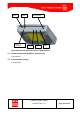
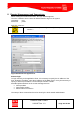
Table Of Contents
- 1 Introduction
- 2 ClearFill®Star System Description
- 3 System Design Guidelines
- 3.1 CDMA Basics (in preparation)
- 3.2 Required information for system design
- 3.3 Design step by step
- 3.4 Estimated RF Coverage per RRH
- 3.5 Right-sizing - the beacon feature (in preparation)
- 3.6 Capacity demand - number for BSIs (in preparation)
- 3.7 System Architecture
- 4 System Installation
- 4.1 General
- 4.2 System Installation (Hardware Installation)
- 4.3 Installation Radio Remote Head (RRH)
- 4.4 Installation Gigabit Ethernet Switch (GES)
- 4.5 Installation Base Station Interface (BSI)
- 4.6 Installation NMS Server (Hardware)
- 4.7 Commissioning of NMS
- 5 NMS Overview
- 5.1 Introduction
- 5.2 Starting the NMS
- 5.3 Tools and Utilities of NMS server
- 5.4 Main Window of NMS Application Client (structure)
- 5.5 The NMS client functionality
- 5.6 Right Click Menus
- 5.7 RRH Configuration
- 5.8 BSI Configuration
- 6 Configuration Management
- 7 System Supervision
- 8 Remote Management and Supervision
- 9 Operational used cases/Maintenance
- 10 System Specifications and Technical Data
- 11 Conformance Statements
- 11.1 United States
- 11.1.1 Introduction
- 11.1.2 Federal Communications Commission (FCC)
- 11.1.3 FCC Part 15 Class A
- 11.1.4 RF approval
- 11.1.5 IEC product safety conformance
- 11.1.6 Indoor applications
- 11.1.7 Antenna exposure
- 11.1.8 Radiofrequency radiation exposure Information
- 11.1.9 Packaging collection and recovery requirements
- 11.1.10 Recycling / take-back / disposal of products and batteries
- 11.2 Canada
- 11.1 United States
- 12 Appendix

ClearFill Star CDMA
1100187 Rev. 1.0
Page 126 of 152
7.4.2 RRH
The following functions are monitored and communicated to the NMS:
DL output power level (composite).
Ambient temperature inside RRH (Threshold is configurable via NMS.
An alarm is generated when threshold is exceeded.)
Power consumption of RRH (Threshold is configurable via NMS.
An alarm is generated when threshold is exceeded. This information is provided to
the NMS by the GES (PoE functionality).)
Status of synchronization to BSI
UL input power level & Protective circuits
RF Packet loss
Running status
IP connectivity
The following information are reported to the NMS
Interferer protection active / inactive
AGC active / inactive (The threshold of the AGC is defined by the gain setting of the
RRH.)
Input signal power level within selected CDMA channel
Data reception status (signalizes that the RRH receives Ethernet packets from GES).
Locally LED indication of RRH status (see Figure 41):