Handbook ClearFill®Star CDMA ClearFill Star CDMA 1100187 Rev. 1.
The following manual is written by RFS for the handling of the ClearFill®Star System. Please utilize your ClearFill®Star System only as described below and after you have read this manual carefully. If you act without authority, RFS cannot be held responsible for any sequences of such operations. Unauthorized actions can cause dangers and damages. In case of doubts, please consult RFS before. All information contained herein is the property of RFS.
Table of Contents Table of Figures Table of Charts 1 Introduction 1.1 General 1.2 Conventions in this Manual 1.3 Standards Conformance 1.4 Firmware Release 2 ClearFill®Star System Description 2.1 General description 2.1.1 2.1.2 2.1.3 7 9 10 10 12 12 12 13 13 Supported Services Identification of System System Structure (deployment architectures) 15 15 16 2.2 Unit description 2.2.1 2.2.2 2.2.3 2.2.
3.7.1 3.7.2 3.7.3 3.7.4 Rules from the Ethernet World Gigabit Ethernet Switch Example system architecture System feeding 49 49 50 50 4 System Installation 4.1 General 4.1.1 4.1.2 4.1.3 4.1.4 4.1.5 4.1.6 4.2 4.3 4.4 4.5 4.6 4.
.8 BSI Configuration 5.8.1 114 Fault Management 115 6 Configuration Management 6.1 Introduction 6.2 Change settings and system parameters 6.2.1 6.2.2 6.2.3 6.2.4 7 7.1 7.2 7.3 7.4 120 120 122 122 124 124 124 124 124 BSI RRH 125 126 Alarm management (graphics, analysis etc.) External alarm routing Remote Management and Supervision Operational used cases/Maintenance Introduction Swap faulty devices 9.2.1 9.2.2 9.2.3 9.2.4 9.3 9.4 9.5 9.6 9.
10.2.3 10.2.4 RRH GES 145 145 10.3 Environmental Conditions 10.3.1 10.3.2 146 Operations Transportation & Storage 146 146 11 Conformance Statements 11.1 United States 11.1.1 11.1.2 11.1.3 11.1.4 11.1.5 11.1.6 11.1.7 11.1.8 11.1.9 11.1.
Table of Figures Figure 1 ClearFill®Star system component distribution.................................................................. 10 Figure 2 Typical deployment topology of a ClearFill®Star network ................................................ 13 Figure 3 Signal flow of ClearFill®Star ............................................................................................. 14 Figure 4 Point of Interconnection (POI) device ........................................................................
Figure 46 Switches ......................................................................................................................... 82 Figure 47 Map View for Non ClearFill devices................................................................................ 83 Figure 48 ClearFill®Star objects map ............................................................................................. 84 Figure 49 Unconfigured Devices Map........................................................................
Table of Charts Table 1 Ethernet Transport Media .................................................................................................. 20 Table 2 Typical attenuation for different materials (source: Wireless Valley) ................................. 25 Table 3 Typical attenuation for different building types (source: Wireless Valley).......................... 26 Table 4 Examples for Propagation Coefficient (source: Wireless Valley).......................................
1 Introduction This document describes the ClearFill®Star system and its components. 1.1 General ClearFill®Star is an innovative, digital, IP-based wireless indoor coverage solution. ClearFill®Star is a unique low-cost approach that improves indoor cellular service by converting radio coverage into an IP based Ethernet application. It is based on wireless, Ethernet, and packet technology.
Advantages of ClearFill Star system versus a typical distributed antenna system: Lower costs for hardware and installation: Installation costs are reduced by the use of existing infrastructure. All remote radio heads / active antennas (RRH) are powered via CAT5 cables and the Power of Ethernet (PoE) functionality that eases the installation considerably. CAT5 cable (+fiber) versus coaxial cable (+fiber). Gig-E components versus RF components.
1.2 Conventions in this Manual This check mark means there is a note of interest and is something you should pay special attention to while using ClearFill®Star. This exclamation point means there is a caution or warning and is something that could damage your property of ClearFill®Star. This question mark provides you with a reminder about something you might need to do while using or administrating ClearFill®Star. 1.
2 ClearFill®Star System Description 2.1 General description In order to leverage the commonly available data network infrastructure, ClearFill®Star uses the same local area network (LAN) topology. A LAN in a typical office building is laid out in a tree topology. The base of the tree is the main telecommunication/equipment room with the Ethernet switches and routers. It usually accommodates the connection to the outside world.
the building. One or more external antennas can be connected to an RRH through a short RF cable or directly on the housing. Power for the RRHs is provided over CAT-5 cables using the power-over-Ethernet (PoE) 802.3af standard. Figure 3 shows a schematic signal flow from BTS to RRH.
2.1.1 Supported Services The ClearFill®Star system supports the following services: CDMA2000 1xRTT systems complying to C.S0002 up to and including Release A EvDO Release A 1.25 MHz applications Frequency Band Class 0 (800 MHz band, sub-bands 0,1 and 2) Frequency Band Class 1 (1900 MHz band) 2.1.2 Identification of System This chapter gives a short overview of the ClearFill®Star components. Please see chapter 2.2-Unit description for a more detailed description of each system element. 2.1.2.
Figure 6 Remote Radio Head (RHH) device 2.1.2.4 Ethernet Infrastructure incl. Gigabit Ethernet Switched (GES) The infrastructure for data transport is based on 1Gigabit Ethernet Switches (GES). Two kinds of cables can be used for the interconnection: CAT5 (or higher) for distances of maximum 100m (300ft) and optical fibers for longer distances. The GES support Power over Ethernet (PoE). Figure 7 Gigabit Ethernet Switch (GES) device 2.1.2.
(a) Star c onfiguration RRH RRH BSI GES GES RRH BSI RRH RRH (b) Tree configuration RRH GES BSI RRH GES RRH BSI RRH RRH Sector 1 Sector 2 Figure 8 General deployment architectures: (a) star configuration (one sector with 5 RRH) and (b) tree configuration (sector 1 with 3 RRH, sector 2 with 2 RRH). ClearFill Star CDMA 1100187 Rev. 1.
2.2 Unit description 2.2.1 Base Station Interface (BSI) The connection to the BTS is established through an RF interface. The RF interface allows ClearFill®Star to support any manufacture’s BTSs. The central task of the BSI is to convert the downlink radio signals into outgoing Ethernet packets and to convert incoming Ethernet packets into uplink radio signals.
The simplexed twin BSI rack supports a carrier capacity of 2 CDMA carriers (realized via two separate BSI in one housing). The Simplexed Twin BSI can be fed by two external power supplies (one for each BSI). The external power supply port is at the rear side of the housing. Minimum spacing of two RF channels that are supported: 2.5MHz. The frequency band and channel allocation are controlled separately for each BSI unit via NMS.
Name 1000BASE-T Medium unshielded twisted pair Distance 100 meters (300 ft) 1000BASE-SX multi-mode fiber 500 meters (1500 ft) 1000BASE-LX single-mode fiber 5 km (3 mi) Table 1 Ethernet Transport Media Signal distribution between other entities (e.g. BTS-POI, POI-BSI, and RRH-antenna) is realized by RF connection.
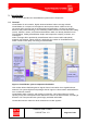
2.3.2 Sectorization The sectorization is configured via the GES. The procedure for VLAN configuration is described in section 4.7.3.4-VLAN Configuration of GES. In a system containing several BSIs the assignment of each RRHs to a BSI (sectorization) is configurable by VLAN (Figure 10). The VLAN configuration / sectorization is done via NMS. RRH .. .. RRH BSI 1 VLAN1 BSI 2 .. .. Transport RRH .. .. Network RRH BSI n RRH VLAN2 .. ..
2.3.3 Guided Hard Handover (Pilot Beacon Functionality) The RRH has to be able to generate a pilot beacon signal in order to guide the hard handover. The guided hard handover is accomplished by a pilot beacon generated by the RRH. A typical realization of the guided hard handover from/to 5 outdoor carriers to/from one dedicated indoor carrier is shown in Figure 11.
3 System Design Guidelines 3.1 CDMA Basics (in preparation) 3.1.1 Data (in preparation) 3.1.2 Voice (in preparation) 3.2 Required information for system design A successful and reliable RF-design is based on many different parameters and assumptions and cannot be described completely in this handbook. The goal of indoor system design is to meet the requirements for excellent performance and QoS. Understanding requirements should include, but not be limited to: Capacity vs.
3.2.2 Coverage area / Architecture drawings For optimizing a system design it is essential to have knowledge about the areas to be covered. A typical indication for the area to be covered is the reception probability: -85dBm@95%RP means that 95% of the Building has to get covered with a signal strength level better -85dBm. Typical values for the minimum signal strength level are in the range of 85dBm to 95dBm, a reception probability of 98% represents a very high demand.
The following typical wall attenuations were observed: Type Attenuation [dB] Thin concrete wall - 10cm (4 inches) 5 Thick concrete wall - 13cm (5 inches) 13 External wall front with windows 8 External wall front without windows 10 Porous concrete 4 Dry wall, sheetrock 1-2 Wood structure, wood door 1 Glass 2 Concrete floor 13 Brick Wall - 10cm (4 inches) 4 Brick Wall - 6cm (2 inches) 3 Partitions metal 1-2 Plastic structure 0.
Statistical models are helpful if the type of building can be classified: Model Name Path Loss Equation [dB] Retail Store PL (d) = 22 Log(3.28*d) + 20.1 Suburban Office Bldg - Open Floor Plan PL (d) = 24 Log(3.28*d) + 19.1 Suburban Office Bldg - Soft Partitions PL (d) = 28 Log(3.28*d) + 17.0 Suburban Office Bldg - Hard Partitions PL (d) = 30 Log(3.28*d) + 16.0 University PL (d) = 0.6232(d)+ 63 Motorola Cluttered PL (d) = 0.594(d) + 71 Motorola Uncluttered PL (d) = 0.
130 120 110 Path Loss (dB) 100 90 80 70 60 50 15 25 35 45 55 65 75 85 95 105 115 125 135 D istan ce (m ) Su b u rb a n O ffice Bld g .o p e n Pla n Su b u rb a n O ffice Bld g . So ft p a rtitio n Su b u rb a n O ffice Bld g . Ha rd p a rtitio n Mo to ro la C lu tte re d Mo to ro la Un clu tte re d F re e Sp a ce (@ 8 9 4 MHz) Figure 12 Path loss models (source: Wireless Valley) Nevertheless it is very important to check possible locations for the antennas and the equipment.
3.2.3 Type of Building ClearFill®Star is a confined area coverage solution, applicable primarily to buildings. Building types: Enterprise Office building Airport Residential Hotel Hospital Fairground Shopping Mall Garage, Car Park area Building topologies: Isolated Building Campus areas Systems for enterprise buildings are more challenging to design due to the construction with concrete walls, concrete pylons and many obstacles like metallic racks, machinery, storage areas, etc.
3.2.4 Number of Users One CDMA channel can handle up to 56 users at the same time. A ClearFill®Star BSI supports the capacity of 1 CDMA carrier. If more capacity is required, additional CDMA carriers can be designed to overcome capacity limitations. Fairgrounds, theatres, stadium areas, meeting rooms and campuses are areas that might require capacity extension. Capacity planning has to be discussed with the network operator, responsible in general for the Base Transceiver Station.
3.2.5 Typical parameters Typical parameters for the system design are: Required signal strength level for CPICH: -80dBm…-85dBm Required signal strength level for CPICH: (Strong outdoor signal present) -70dBm…-75dBm Reception probability (typical): 90%..95% Coverage area for 1 RRH (typical): 2,500 sqm (25,000 sqft) Typical propagation loss for antenna radius 28m (92 ft): (Office area with sheetrock walls) 3.
Example 1: By using the standard propagation model, 2 Remote Radio Heads can cover a rectangular office floor with the dimensions 100m x 50m (330 ft x 165 ft). Example 2: For an office floor with the dimensions 100m x 100m (330ft x 330ft), 4 RRHs should be used. ClearFill Star CDMA 1100187 Rev. 1.
Up to 24 RRHs can be connected to a summing GES. The number of RRHs is independent from the type of service (voice or data) for CDMA. At least 24 RRHs for voice 3G1x, 24 RRHs for data transmission EV-DO and the required number of RRHs for the guided hardhandover- service, called the beacon feature, can be connected to a summing GES. For detailed information concerning summing modes please refer to section 3.5. 3.3.
3.3.4.1 Example 1 for Twin BSI configuration 1 carrier for data and 1 carrier for voice: 1 carrier CDMA 1900 3G1X AND 1 carrier CDMA 1900 EV-DO Figure 15 Example 1 for Twin-BSI configuration Twin BSI configuration for 2 carriers/each service: 2 carriers CDMA 1900 3G1X OR 2 carriers CDMA 1900 EV-DO Figure 16 Example 2 for Twin-BSI configuration ClearFill Star CDMA 1100187 Rev. 1.
3.3.5 Number of GES The Gigabit Ethernet switch supports the functionality of the Remote Radio Heads and the NMS. All GES-settings are controlled and realized via NMS. The GES provides Power over Ethernet (POE) to the RRHs and the BSI. The GES can handle RRHs supporting voice, data and beacon service and BSI’s. Up to 12 Ethernet ports are available at the GES. Ports 11 and 12 can be used as optical ports, by using these ports only ports 1 to 10 can be used for an Ethernet based connection.
The number of GES depends on the RRH quantity and can be affected by distance. A good design is to place a GES in a central location within a group of RRHs (up to 11 RRHs, because one port is needed for the connection to the next GES). This minimizes the distance to each RRH. It is essential that the Ethernet cable length of 100m (330ft) is not exceeded. RRH Summing for Uplink: A summing function is included in the RRH, it sums the UL data streams for data or voice of up to 8 RRHs of the same GES.
3.3.5.1 ClearFill®Star example configuration 1 for PCS1900: 1 Carrier 3G1x (Voice) 1 Carrier EV-DO (Data) 1 Entrance covered with Beacon feature Area to be covered (typical for office) 2,500sqm (25,000 sqft) Figure 18 ClearFill®Star setup example 1 ClearFill Star CDMA 1100187 Rev. 1.
3.3.5.2 ClearFill®Star example configuration 2 for PCS1900 1 Carrier 3G1x (Voice) 1 Carrier EV-DO (Data) 1 Entrance covered with Beacon feature Area to be covered (office) 10,000sqm (100,000 sqft) (4 RRH with 2,500sqm/each) Figure 19 ClearFill®Star setup example 2 ClearFill Star CDMA 1100187 Rev. 1.
3.3.5.3 ClearFill®Star example configuration 3 PCS1900 Max configuration for 1 GES 1 Carrier 3G1x (Voice) Area to be covered (typical for open office) 25,000sqm (250,000 sqft) (10 RRHs with 2,500sqm/each (25,000 sqft/each)) Figure 20 ClearFill®Star setup example 3 ClearFill Star CDMA 1100187 Rev. 1.
3.3.5.4 ClearFill®Star example configuration 4 for PCS1900 2 Carriers 3G1x (Voice) 2 Carriers EV-DO (Data) Area to be covered (typical for open office) 10,000sqm (100,000 sqft) Carrier allocation Figure 21 ClearFill®Star setup example 4 ClearFill Star CDMA 1100187 Rev. 1.
3.3.5.5 ClearFill®Star example configuration 5 for PCS1900 1 Carrier 3G1x (Voice) 1 Carrier EV-DO (Data) 2 Entrances covered by Beacon feature Area to be covered (typical for open office) 20,000sqm (200,000 sqft) (8 RRHs/each service with 2,500 sqm/each (25,000 sqft/each)) Figure 22 ClearFill®Star setup example 5 ClearFill Star CDMA 1100187 Rev. 1.
3.4 Estimated RF Coverage per RRH 3.4.1 Propagation Model (Free Space Loss) A simplified model is used to calculate the propagation losses for in- and outdoor environments. Free-space propagation conditions are assumed. Obstacles penetrated in direction of transmission are causing additional RF losses. Due to relatively short ranges in buildings, line-of-sight conditions can be assumed which are interrupted by obstacles. Consequently, impact of scattering is neglected.
Environment Description PC Low-Band < 1GHz PC High-Band > 1GHz Free Space Corridor 2.0 2.0 Open: With very few RF obstacles Parking Garage, Convention Center 3.37 3.01 Moderatly Open: With low to medium amount of RF obstacles Warehouse, Airport, Manufacturing 3.5 3.2 Mildly Dense: With medium to high amount of RF obstacles Retail, Office Space with approx. 80% cubes and 20% hard-walled offices 3.61 3.
3.4.1.2 In-Building Path Loss For in-building applications, the PC has to be chosen correctly as already mentioned above. In addition to free space propagation, additional wall losses have to be introduced. Guidelines for different kind of wall types are presented in Table 5.
3.4.2 Power Level Estimation (Link Budget) This section describes the calculation of the expected UL and DL reception power levels. For this sample investigation a standard model of an area of 50 x 50 sqm (25,000 sqft) (resulting in a coverage radius of 34m (110 ft)) has been chosen to provide coverage and capacity for. The model to calculate the propagation losses in indoor environments is described in section 3.4.1.
3.4.2.1 Downlink A coverage radius of a RRH in DL is calculated to be 28 m assuming 14 dBm composite output power of the RRH, a composite reception level of -85 dBm at 95 % reception probability at the handheld and the above given propagation model. RRH Output Power Level 14.0 dBm CPICH Power Level 7.0 dBm RRH Antenna Gain 0.0 dBm CPICH EIRP 0.0 dBm Frequency 1950.00 MHz min. Distance max Distance RRH Antenna Height 3.50 m Fading Margin 2.00 dB Body Loss 3.00 dB Slope Factor 2.00 2.
3.4.2.2 Uplink For the mobile, the output power and dynamic range was assumed as shown in Table 8.
The calculation result for the UL reception power levels is summarized in Table 9. Cell Distance handheld RRH Reception level with max power at handheld Reception level with min power at handheld PCS 2.5 m 34 m 2.5 m 34 m -18dBm -67dBm -29dBm -79dBm -95dBm -144dBm -102dBm -152dBm GSM-850 Distance handheld RRH Reception level with max power at handheld Reception level with min power at handheld 2.5 m -12 dBm -40 dBm GSM-1900 6.5 m -20 dBm -48 dBm 34 m -61 dBm -89 dBm 2.
3.4.
3.7 System Architecture 3.7.1 Rules from the Ethernet World 3.7.1.1 CAT5 lengths Maximum CAT5 (or higher) cable length is 100 m (300 ft). 3.7.1.2 Optical lengths Maximum length of the multi mode fibers is 550 m (1650 ft) 3.7.1.3 Cascade Rules: Up to 4 Levels, including the main switch connected to the BSI. It is mandatory that all RRHs have same number of switches on the signal path to the BSI. This is applicable for each VLAN.
3.7.3 Example system architecture 3.7.4 System feeding Adding Capacity by Growing Sectors on In-Building Solutions with ClearFill®Star: Unlike in the Macro Network, it is recommended that capacity be grown by adding sectors to the inbuilding system. The reason for this is increasing the number of sectors improves the ability to locate users within a building. Also, adding sectors to a ClearFill®Star System is less expensive than adding carriers.
connectors), 1900 MHz band signal and splits it into two simplexed signals to connect to two BSIs. Each BSI has simplexed (forward, reverse separate) RF connectivity (two connectors per band class). Each BSI is a single carrier device (by configuration) but is capable to accept a multiple RF carrier signal: The BSI discerns (by configuration) the specific RF carrier which it shall convert to Ethernet. If two in-band (e.g.
4 System Installation 4.1 General 4.1.1 Safety Considerations PTFE and PTFE Composite Materials: Materials should never be heated to the point where smoke or fumes are evolved. Any person feeling drowsy after coming into contact with PTFE, especially dust or fumes should seek medical attention. 4.1.2 Packing List Each unit comes with a packing list. Please check the completeness of each unit and contact RFS directly to claim any missing parts.
4.1.4 Installation Locations and requirements All RFS ClearFill®Star units are designed to be installed indoors. The RFS ClearFill®Star equipment operates over CAT5, CAT-5E or CAT6 cable of type unshielded twisted pair (UTP), foiled twisted pair (FTP) or screened twisted pair (ScTP), with shielded RJ-45 connectors; or Single-mode fiber (SMF) or multi-mode fiber (MMF) cable with SC/APC fiber connectors throughout the fiber network, including fiber distribution panels.
4.2 System Installation (Hardware Installation) The following has to be carefully observed during installation, because most of the following issues are the cause of malfunctions: Faulty cabling/connector Dirty connectors and ports Malfunction of one or more components Antenna, base station, or repeater problem External RF interface Tripped circuit breaker Equipment is not grounded Faulty cabling is the cause of a majority of problems.
4.3 Installation Radio Remote Head (RRH) Before beginning the installation of the RRH, all RF cables (if applicable) and Ethernet cables should be installed. Please follow the general procedure for installing the RRH as it is described below. It is important that the above installation instructions are followed in the sequence presented to ensure a correct and save installation. 1. 2. 3. 4. 5. 6. 7. 8. 9. 10. Transport the RRH to the installation site in its packaging.
4.4 Installation Gigabit Ethernet Switch (GES) GES is designed to be mounted into a 19” rack. Remove the GES from its packaging and check for obvious signs of physical damage. If the unit is physically damaged do not proceed with the installation. Check the packing for completeness according to the packing list. To mount the GES to a rack, the angles that are delivered with the accessory kit have to be fixed to the housing. Voltage of mains must 115/230 VAC ± 10%.
4.7 Commissioning of NMS After all steps above have been done the NMS server can be started. The elements of the system should be started (supplied with power) in this sequence: NMS server Root Switches (+BSI) Access Switches (RRHs are also started due to PoE) 4.7.1 Start of NMS Server 1. Press left most red button on front panel of NMS server until the fan power led starts to glow (green led). 2. The windows operating system starts.
4.7.3.1 IP Address Configuration First of all the IP configuration has to be done for the whole network. The GES are set to fixed IP addresses, the BSIs and RRHs are using dynamic IP addresses. The NMS server is running a DHCP server to provide the dynamic IP participants with IP addresses. All GES are delivered with the same default IP address: 192.168.1.1. Because of that the GESs have to be switched on one after another.
Figure 27 GES IP Configuration Menu 6. Leave DHCP setting to “Disable” (by drop down menu). 7. set IP address to the desired value (unique IP address within the network). 8. Set Subnet Mask to: 255.255.255.0 9. Set Default Gateway to: 192.168.1.4 (default address of NMS server) 10. Leave DNS server to: 0.0.0.0 11. Click on Apply. 12. Click on Reboot in left hand side menu. 13. Click on “Save and Reboot” in the right hand side window. Repeat this procedure with every GES in the network.
4.7.3.2 SNMP Configuration of GES The Switches have to communicate via SNMP with the NMS server. This chapter shows how to setup a GES for SNMP support. Procedure to set a GES to support SNMP: 1. Open Microsoft Internet Explorer. 2. Enter the address “http://192.168.1.1” in the address window. 3. Login to the switch by using Username: admin Password: admin 4. Click on SNMP in the left-hand sides menu. See Figure 28for the SNMP menu that appears. 5. Set SNMP to: enable 6. Set Get Community to: public 7.
4.7.3.3 STP configuration of GES The ClearFill®Star system uses the spanning tree protocol. It has to be activated in every GES. Procedure to set a GES to support STP: 1. Open Microsoft Internet Explorer. 2. Enter the address “http://192.168.1.1” in the address window. 3. Login to the switch by using Username: admin Password: admin 4. Click on STP in the left-hand sides menu. 5. Click on the appearing sub menu Configuration, see Figure 29 for the STP menu that appears. 6.
4.7.3.4 VLAN Configuration of GES The ClearFill®Star system uses the tag based VLAN mode. There are three different tags used in the ClearFill®Star network: NMS Voice Data The three tags have to be configured in every GES. Also the support of every VLAN port has to be setup for every port of the GES. Therefore it is mandatory that a good documentation of the installed hardware is available. It should have been created during the hardware installation process (see section 4.2).
Figure 30 GES tag based VLAN configuration menu for NMS 17. Click on Add. 18. Set VLAN Name to: Voice 19. Set VID to: 2 20. Set SYM-VLAN to: Enable (via drop down menu) 21. Set GVRP Propagation to: Disable (via drop down menu) 22. Activate every port that is connected to a device that is going to operate within the voice sector and activate ports 11 and 12. The last two ports are needed to route the information through the cascaded GESs. 23. Click on Apply. ClearFill Star CDMA 1100187 Rev. 1.
Figure 31 GES tag based VLAN configuration menu for Voice 24. Click on Add. 25. Set VLAN Name to: Data 26. Set VID to: 3 27. Set SYM-VLAN to: Enable (via drop down menu) 28. Set GVRP Propagation to: Disable (via drop down menu) 29. Activate every port that is connected to a device that is going to operate within the data sector and activate ports 11 and 12. The last two ports are needed to route the information through the cascaded GESs. 30. Click on Apply. ClearFill Star CDMA 1100187 Rev. 1.
Figure 32 GES tag based VLAN configuration menu for Data Figure 33 GES tag based VLAN configuration menu 31. Click on VLAN on the left hand side menu 32. Click on the sub menu Tag Rule ClearFill Star CDMA 1100187 Rev. 1.
Figure 34 GES VLAN Tag Rule menu 33. Configure each port for of the GES according to its specific use. 34. Mark each port by clicking on the appropriate line and than click on Edit. Figure 35 VLAN Tag Rule Edit Menu 35. Afterwards set the Role drop down menu according to the use of the port: a. Ports that are used for the connection of an RRH or a BSI are set to “Hybrid”. b. Ports that are used to connect the NMS/PC are set to: “Access”. c.
36. All other fields are set to default values: a. PVID = “1” b. Rule 1 = “disable” c. Rule 2 = “disable” d. “Untag VID” = “1” 37. To finish and store the GES configuration click on Reboot on the left hand side menu. 38. Click on “Save and Reboot” in the left hand side menu. Repeat this procedure with every GES in the network. Start with the switch that is closest to the BSIs (root switch) and follow the network topology to the GES that has the longest topological distance to the BSI (access switches).
Figure 36 Web NMS Launcher Window 5. User is quoted for a password, default user name is “root”, default password is “public” (see Figure 37 ClearFill®Star authentication). After first login please change password according to corporate security guidelines. Figure 37 ClearFill®Star authentication 6. The client application appears. Open the Network Maps View (left side of screen), click on “Switches”. In the appearing menu all GES switches that have been installed before should be shown (see Figure 38).
Figure 38 Network Map – Switches 7. Open the Uncofigured RRH / BSI Nodes View. It should contain all RRH and BSI nodes that were installed before (see Figure 39). If not consult the network administrator. ClearFill Star CDMA 1100187 Rev. 1.
Figure 39 Network Map – Unconfigured RRH / BSI Nodes 4.7.4 System optimization In preparation ClearFill Star CDMA 1100187 Rev. 1.
5 NMS Overview 5.1 Introduction The ClearFill®Star Application Client presents the system management information in two different approaches. The first approach is the visual representation of the network elements in the form of graphical maps, which capture the topological or geographical organization of these elements. The second approach is an easy-to-access dynamic data representation with tables that list the aspects that are managed by ClearFill®Star NMS.
5.3 Tools and Utilities of NMS server This chapter describes the tools and utilities that are installed on the NMS server on delivery. 5.3.1 The Web NMS Launcher The Web NMS Launcher is the central interface to start the NMS Application Client or any other RFS tool or utility. It is started by clicking on Web NMS Launcher icon which is placed on the windows desktop. See Figure 40 for the Web NMS Launcher window.
Simulations and Browsers For expert Modus Administrator Tools For expert Modus Reinitialize ClearFill NMS Will clear all data bases and the log files on the server.
5.3.2.1 General Tab Figure 41 Discovery Configurator – General Tab In the General tab, the following options are available. Activate or deactivate them by clicking on the check mark symbol next to them. AutoDiscovery NMS does automatically add each node on the specified network Rediscover Already Discovered Enable the NMS to rediscover nodes that have already been discovered to check for status changes. Discover LocalNet NMS to discover nodes attached directly to the NMS server.
Further more there are two buttons in the General Tab: Initial Parameters Allows the user to manually define the parameters by which the NMS discovers the nodes on the network with respect to the following Discovery interval: o Rediscovery interval o ICMP Ping retries o SNMP Timeout o SNMP Retries o NativePing Timeout o NativePing Retries Rediscovery Open the Rediscovery Scheduler which allows the user to setup rediscovery at regular intervals, specific dates or days of the week. 5.3.2.
In the Network Discovery tab, following options are available: Network to search Checkmark each network to search for ClearFill Star Elements in the Discover column. Discover o Entire Network For a complete discovery. This may take about 30 minutes o Set of Nodes Define a range of IP addresses to be searched with net mask, the start IP and end IP DHCP SNMP o SNMP Properties 5.3.2.4 Node Discovery Tab The Node Discovery tab allows the user to add single nodes manually.
5.3.3 ClearFill Star Client Login Window Upon startup of the ClearFill Star Client, the login window appears. The user is asked to enter a user ID and password to log in to the system. Figure 43 Login Screen Default account: Username: root Password: public And click “Connect” There is also an option to login remotely, that option is described in section 7. The remote options are accessible via the Advanced button, which is ignored in this section. ClearFill Star CDMA 1100187 Rev. 1.
5.3.4 Logs Window Upon start-up of the Application Client the Logs window appears. This window displays general information on the current system and will display feedback from the NMS with regard to actions and services. It also displays system error messages. Figure 44 Logs Window ClearFill Star CDMA 1100187 Rev. 1.
5.4 Main Window of NMS Application Client (structure) The ClearFill®Star Application Client is the main tool to configure and maintain the ClearFill®Star System. It is started via the Web NMS Launcher (see section 5.3.1). After having started the NMS Client, two main windows appear: The Application Client with the default display for the Network Maps The Logs window (see section 5.3.
5.4.1 The Menu Bar The menu bar is placed at the top edge of the display area. The menu bar differs from screen to screen based on the functions and also based on privileges of logged in user. For instance, the Fault Management module has additional menu items for users with administrator rights, such as Actions and Custom Views. But certain menu items, also available for users with standard rights. 5.4.
5.4.3 The Display Pane The display pane is on the right-side of the Application Client window and appears as a window within the main window. This panel shows details of the tree node that is selected in the tree pane (see section 5.4.2). If for example Fault Management and on one of the appearing nodes is selected in Tree Pane (like Network Events or Alarms), the information of the selected node is shown in the Display pane. 5.4.
5.5.1.1 Switches Each discovered switch is presented as a schematic image of a switch front panel. Figure 46 shows an example of the switch view (with two switches in the network). Figure 46 Switches Every single port on the schematic switch drawing is either orange (no connection detected) or green (connected). In the lower left corned the IP address of the switch is visible. ClearFill Star CDMA 1100187 Rev. 1.
5.5.1.2 Non-CFS Objects Objects that have been found on the network and do not match the ClearFill®Star criteria are listed in the Non-ClearFill Objects tab. These objects may include the following: NMS appliance NMS Client Routers Printers PC and any other network device Figure 47 shows an example of a map view for Non-ClearFill objects: Figure 47 Map View for Non ClearFill devices ClearFill Star CDMA 1100187 Rev. 1.
5.5.1.3 CFS Objects Objects that meet the ClearFill®Star criteria are listed under ClearFill Objects. Listed devices include: BSI RRH Switches Each node is presented with these features in every map view: IP Address Online / Offline status (Active / Failed) Figure 48 shows an example of a map view with ClearFill®Star objects. Figure 48 ClearFill®Star objects map ClearFill Star CDMA 1100187 Rev. 1.
5.5.1.4 Unconfigured RRH/BSI Node(s) This map displays all BSIs and RRHs that are not configured for any sector. Devices shown in this map have their sector id set to zero. See Figure 49 for an example view. Figure 49 Unconfigured Devices Map ClearFill Star CDMA 1100187 Rev. 1.
5.5.1.5 Failed Systems This map shows graphically each failed ClearFill®Star element on the network. Figure 50 shows an example for the failed nodes map view. Figure 50 Failed Systems map ClearFill Star CDMA 1100187 Rev. 1.
5.5.1.6 Configured RRH/BSI Node(s) The configured RRH/BSI nodes view shows all devices that are already configured. See Figure 51 for a map view of the configured ClearFill®Star devices. Devices are considered to be configured when the sector id is configured to be unequal zero. Figure 51 Configured BSIs and RRHs map view ClearFill Star CDMA 1100187 Rev. 1.
5.5.2 Fault Management 5.5.2.1 Network Events All network events are logged. They are displayed in the network events tab. See Figure 52 for an example for the network events view. The background color of each event informs users of the nature of the event. Figure 52 Network events view ClearFill Star CDMA 1100187 Rev. 1.
5.5.2.2 Alarms All Alarms are logged and displayed in the Alarms view. See Figure 53 for an example alarms view. Figure 53 Alarms view ClearFill Star CDMA 1100187 Rev. 1.
5.5.3 Provisioning 5.5.3.1 Templates The provisioning tab contains the template collection to provision the ClearFill®Star network elements. The lists of templates available to the user are as follows: AddClearFillObj DeviceConfig FirmwareDownload RemoveSector SectorConfiguration SectorPilotConfiguration See Figure 54 for an example of the provisioning templates view. Figure 54 Templates Display Panel ClearFill Star CDMA 1100187 Rev. 1.
Invoking Provisioning Templates Click on the Provisioning tab Click on the templates child tab. A table of templates will appear in the Display Panel as in the screen shot above. Perform any of the following procedures to start the execution of a template: Right-click a row on the table and select Provision Double-click a row on the table Click a row in the table and from the Templates menu, choose Provision Click a row in the table and press Shift + Ctrl + P 5.5.3.1.
5.5.3.1.2 Device Configuration The DeviceConfig provisioning template allows the user to setup ClearFill®Star elements with a standard default template. See Figure 56 for an example screen shoot. Double click on the template name and follow this walk through. Figure 56 DeviceConfig provisioning template Enter the name of the file to be used for the provisioning. The provisioning file must be in the TFTP directory of NMS server.
5.5.3.1.3 Firmware Download The firmware download template is used to update ClearFill®Star network elements. See Figure 57 for an example screen shoot. Figure 57 Firmware download template ClearFill Star CDMA 1100187 Rev. 1.
5.5.3.1.4 Remove Sector The remove sector template is used to remove the sector from a ClearFill®Star network. This may be done the first time the system is started or later if the sector configurations have to get changed. Double click on the template name and follow the walk through instructions to remove a sector. Figure 58 Remove Sector step 1 Step 1: Enter sector identification with by name or by number.
Figure 59 Remove Sector step 2 Step 2: All devices that belong to the sector are listed. Click on Remove Sector button to remove the configured sector information from the listed devices and thus clear the sector. ClearFill Star CDMA 1100187 Rev. 1.
Figure 60 Remove Sector step 3 Step 3: Finally all removed devices are listed. All tasks that had to be done to remove the sector are listed. The status of each task is also listed. If any task is not in state successful the sector has not been completely removed. Any trouble reports have to be solved before a new sector is configured. ClearFill Star CDMA 1100187 Rev. 1.
5.5.3.1.5 SectorConfiguration The sector configuration template is used to setup new sector. All devices that are supposed to belong to a sector are selected from a list. Afterwards the sector information is written to every selected device. There are three types of sectors: Voice (sometimes including pilot beacons) Data Pilot beacon. This template is used to setup voice and data sectors. It is also used to configure voice sectors that include one or more pilot beacons.
Enter: Sector Name (usually Voice or Data) Sector Number (2 for Data, 3 for Voice) Frequency Band Channel Number Base Station PN Offset Service Type (Voice or Data) Click on next to continue the setup. Figure 62 SectorConfiguration template step 2 Select BSI of sector BSI auto start Click Next to continue setup ClearFill Star CDMA 1100187 Rev. 1.
Figure 63 SectorConfiguration template step 3 Select: RRHs for sector RRH TX Power RX Gain RRH Auto Start A data sector configuration is finished with this step. Add Provision to get directly to step 5. When configuring a voice sector it is possible to continue with the configuration of a pilot beacon from here. Click on Select Pilot Nodes for Sector to continue with pilot beacon selection (step 4). ClearFill Star CDMA 1100187 Rev. 1.
Figure 64 SectorConfiguration template step 4 Select the RRH to be configured for pilot beacon use. Click on Provision to finish the sector configuration. ClearFill Star CDMA 1100187 Rev. 1.
Figure 65 SectorConfiguration template step 5 The final screen of the sector configuration shows if the sector configuration has been executed successfully. Any failed steps are listed here. ClearFill Star CDMA 1100187 Rev. 1.
5.5.3.1.6 SectorPilotConfiguration This template is used to configure sectors that provide pilot beacon only functionality. Follow this walkthrough to configure an RRH for pilot beacon use. Figure 66 SectorPilotConfiguration template step 1 Step 1: Enter Sector Name Sector Number Frequency Band Channel Number Base Station PN Offset ClearFill Star CDMA 1100187 Rev. 1.
Figure 67 SectorPilotConfiguration template step 2 Step 2: Select BSI for the sector Enter BSI Auto Start ClearFill Star CDMA 1100187 Rev. 1.
Figure 68 SectorPilotConfiguration template step 3 Step 3: Select Pilot Beacon RRHs. Click on Provision Pilot Sector to finish setup of pilot beacon. 5.5.3.2 Activity List Every activity is stored in the activity list. It can be used to verify if provisioning was successful. It is possible to view results by double clicking on item and then again by double clicking on the specific task. Results can also be monitored in the Logs Window. Figure 69 Activity List ClearFill Star CDMA 1100187 Rev. 1.
5.5.4 Network Database The Network Database view works in much the same way as the Network Maps view except the format which is textual instead of graphical. The Network Maps (graphical format) are described in section 5.5.1. Click on Application Network Database in the tree pane (left-hand side). Following sub nodes appear: Networks Nodes Interfaces Switches ClearFill Star BSI ClearFill Star RRH The following chapters describe each of those sub nodes. 5.5.4.
The meaning of each value is: 1 = Discovery Yet to Begin 2 = Discovery in Progress 3 = Discovery Finished 4 = Discovery Disabled 5.5.4.2 Nodes This view is used for the node configuration. Nodes can be configured both in the Network Maps and in the Network Database view. Both support the configuration menus that are accessed via right click on the node to be configured. 5.5.4.3 Interfaces All interfaces are displayed and can be managed 5.5.4.4 Switches All switches are displayed and can be managed 5.5.
5.6.1 RRH/BSI Right-Click Options For the RRH,BSI and summing nodes, the right click menus are as follows: Figure 71 RRH/BSI Right Click Menu Managed Object Properties This menu allows the user to edit the managed object properties. Delete Object and Traces This menu allows the user to delete a node’s object and traces in the NMS. Events And Alarms Clicking on Events and Alarms shows the following screen for the node. Configuration This menu leads to RRH Configuration (section 5.6.
5.6.2 Switch Right-Click Menu Right clicking on any switch shows the following menu. Each option opens its respective window. Figure 72 Switch Right Click Menu Managed Object Properties This menu allows the user to edit the managed object properties. Delete Object and Traces This menu allows the user to delete a node’s object and traces in the NMS. HTTP Device Opens an HTTP connection to the switch, the standard browser of the system is started in an extra window.
5.6.3 Network Right-Click Menu In the Network application, it is possible to stop and restart the node discovery application by clicking on the Networks view in the Application Client window as seen below. Right click on the desired network and select either ‘Stop Discovery’ or ‘Start Discovery’ in the context menu. Figure 73 Network right-click menu with stop option Figure 74 Network right-click menu with start option The Discovery Status is displayed in the Network view under ‘Disc Status’.
5.7 RRH Configuration The RRH Configuration screen is accessed via the right click menu. Click on an RRH unit in Network Maps or Network Database view and select Configuration->RRH Configuration. Follow this walkthrough to setup an RRH unit. The upper half of the configuration screen shows the IP address, the running status (online or offline) and the MAC address of the device to be configured. Press Read Device to update the screen by reading the device again.
In the general configuration tab it is possible to set: System location System contact Host Name TX power (dBm) RX Gain Figure 76 RRH Pilot Beacon Configuration Tab In the pilot beacon setup menu it is possible to set: The number of pilot frequencies (use the drop down menu in the lower left corner) 7 pilot frequency windows, depending on the number that has been selected in the drop down menu these are grayed out (unused) or white (settable) RRH PN Offset BTS PN Offset ClearFill Star CD
Figure 77 RRH Sector Configuration Tab The sector configuration tab consists of: Sector Name Band BSI Node MAC Dest MAC Sector Number Channel Delay in micro seconds ClearFill Star CDMA 1100187 Rev. 1.
Figure 78 RRH Status Tab The status menu consists of: RF Output Power RX Channel Power EEPROM Check Status GP Bad Frame Error Count Packet Drop Count Missing Sample Count Bad CDMA Packet Count ClearFill Star CDMA 1100187 Rev. 1.
5.8 BSI Configuration The BSI Configuration screen is accessed via the right click menu. Click on a BSI unit in Network Maps or Network Database view and select Configuration->BSI Configuration. Follow this walk through to setup a BSI unit. The upper half of the configuration screen shows the IP address, the running status (online or offline) and the MAC address of the device to be configured. Press Read Device to update the screen by reading the device again.
Figure 80 BSI Configuration Sector Tab In the sector configuration tab it is possible to see the current setting of Sector name Sector number Band Channel Delay in micro seconds 5.8.1 Fault Management All events (traps) and alarms in a network are shown in the Fault Management applications. These sub nodes are accessible when fault management application has been selected in the tree view.
5.8.1.1.1 Event search options The search option is designed to look for a particular event within the Network Event list. The search operation is performed in the database and is not restricted to the events that are currently visible in the Application Client panel. To search for an event do one of the following actions while in Network Events view: From Edit menu, choose Search. From the toolbar, click Find button. Press Ctrl+F.
5.8.1.2 Event save option The save option is used to save the current range of events displayed in the Event Viewer. The events are saved by following one of these steps: Perform any of the following procedures. From Actions menu, choose Save to File. In the toolbar, click Save. Press Ctrl+I. The Properties dialog box is displayed. Enter the file name in File Name field. Click Save File. A status message is displayed. 5.8.1.
5.8.1.4.1 Network Event View Click Network Events display node in the tree. The network events are displayed in an Event Viewer on the display panel, see screen shot below. Figure 82 Event Viewer All events are displayed in the Event Viewer. Each row in the table depicts an event. The events can be sorted by column (Status, Source, Date or Message) in ascending or descending alphabetical order. Click on the column title to be used for sorting.
5.8.1.4.2 Alarms View In the alarms view a history of alarms is listed. To view only related alarms for only one device you may change to the Event viewer and proceed with these steps: Open the Event Viewer. Click a row whereby you select an event. Perform any of the following procedures. From View menu, choose Alarms. Right-click the row and choose Alarms. Press Ctrl+L. Alarm Viewer with only the alarms related to the selected event is displayed. ClearFill Star CDMA 1100187 Rev. 1.
6 Configuration Management 6.1 Introduction The ClearFill®Star Application Client is the graphical user interface for the configuration management it is running on the ClearFill®Star NMS server or it is running remotely connected to the NMS server. The configuration management is done with the ClearFill®Star Application Client. It is used to configure the elements of the ClearFill®Star network. See chapter 5 for an overview of this tool. 6.
6.2.2.5 Pilot beacon generation and set-up The pilot beacon is configured in the RRH Configuration menu. It is described in section 5.6.1. 6.2.2.6 Switching between CELL and PCS band The switching between CELL and PCS band is done only once during initial sector configuration. The sector configuration is described in chapter 6.2.1. To change the band from CELL to PCS or vice versa the sector has to be cleared by using the template described in section 5.5.3.1.4.
6.2.3 GES The GES is configurable over an own HTTP menu. This menu can be reached by simply opening a browser (e.g. Microsoft Internet Explorer) and entering an “http://” followed by the IP address of the GES. It is also accessible by using the ClearFill®Star Application Client. And change to the menu Application->Network Maps->Switches. Right click on the switch symbol and select (HTTP device). The browser will open automatically, showing the HTTP menu of the switch.
6.2.4.5 Switch off the BSI. The BSI is power supplied by the PoE functionality or an external power supply. When it is supplied over an external power supply the switch off has to be done manually by disconnecting (or switching off) the external power source. When the BSI is supplied by the PoE functionality the switch off can be done via the GES. This is done by following procedure: Use ClearFill®Star Application Client. Change to the menu Application->Network Maps->Switches.
7 System Supervision 7.1 Introduction The system supervision is done by the NMS Server. It stores all events and alarms that are detected within the ClearFill®Star network. 7.2 Supervision GUI The ClearFill®Star Application Client is the graphical user interface for the system supervision. See chapter 5 for an overview of this tool. See chapter 5.8.1 for a detailed explanation of the fault management mechanisms. 7.3 Alarms and faults structure Alarms are classified by severity.
7.4.1 BSI The following functions are monitored and communicated to the NMS: Ambient temperature inside BSI (An alarm is generated when threshold is exceeded.) Status of synchronization to BTS (An alarm is generated when synchronization is lost.
7.4.2 RRH The following functions are monitored and communicated to the NMS: DL output power level (composite). Ambient temperature inside RRH (Threshold is configurable via NMS. An alarm is generated when threshold is exceeded.) Power consumption of RRH (Threshold is configurable via NMS. An alarm is generated when threshold is exceeded. This information is provided to the NMS by the GES (PoE functionality).
LED Status Description of Function Green State LED A blinking state indicates that the processor is operational. This LED also flashes in response to the NMS flash attention LEDs command (used to identify a particular node 1 in the network). A static state (ON or OFF) indicates that the processor is no longer operating correctly, a power-cycle is required to recover from this state. Amber Warning LED.
LED4 Ethernet connector LED5 Reset button LED1 LED2 LED3 Figure 83 Schematic illustration of local RRH interfaces 7.5 Alarm management (graphics, analysis etc.) In preparation 7.6 External alarm routing In preparation ClearFill Star CDMA 1100187 Rev. 1.
8 Remote Management and Supervision When starting the ClearFill Star Client, the login window appears. The user is asked to enter a User ID and Password to log in to the system. Username: root Password: public And click “Connect” There is also an option to login remotely, that option is described in section 7. Figure 84 Advanced Login Screen Remote login To login remotely to the application client, it is necessary to specify the IP address of the host.
9 Operational used cases/Maintenance 9.1 Introduction This chapter provides instructions for the most common use cases. It also provides instructions on how to contact RFS in case of hardware defects. 9.2 Swap faulty devices Please contact RFS in case of broken hardware. The procedure for contacting RFS is described in section RFS Maintenance Services. The following swap procedures assume that a new or repaired device is already available to be swapped. 9.2.1 Swap RRH Swapping procedure for an RRH: 1.
9.2.3 Swap BSI Swapping procedure for a BSI: 1. Disconnect all cables from old BSI. 2. Remove old BSI from rack. 3. Write down MAC address of new BSI and update it in your local setup documentation. 4. Put new BSI into the rack. 5. Connect all cables that were connected to the old BSI to the new BSI. Use exactly the same ports as before. Start ClearFill Star Application Client. 6. Run template AddClearFillObj (see section 5.5.3.1.1) to add the BSI to the network database. 7.
9.5 Change RRH sector allocation A sector allocation cannot be changed. The only way to change it is to delete the existing sector and configure a new sector. Changing procedure for the sector allocation of an RRH: 1. Start ClearFill Star Application Client. 2. Delete old sector with template RemoveSector (see section 5.5.3.1.4). 3. Reconfigure sector by running template SectorConfiguration (see section 5.5.3.1.5). 9.
9.7 Maintenance 9.7.1 Introduction The RFS product line comprises all necessary products to design and build a complete end to end solution for providing RF coverage and best Quality of Service to confined areas as buildings and tunnels. Partly this portfolio consists of active elements like ClearFill®Star system. The following chapters describe the maintenance services (also called after sales services) defined to support the customer in the operation and maintenance of RFS Solutions. 9.7.
9.8 Warranty All active (as well as passive) products of the RFS portfolio are coming with a standard warranty period of 12 months. This warranty can be extended by paying an additional warranty fee. 9.8.1 RFS Maintenance Services Note: The following chapters 9.8.1 – 9.8.4 are general information only. For Alcatel-Lucent customers: To obtain technical support, documentation and training or to submit feedback: The Alcatel-Lucent Online Customer Support (OLCS) website: http://support.alcatel-lucent.
9.8.2 Welcome Center 9.8.2.1 Introduction Purpose of the Welcome Center is to provide a regional single interface to the customer to initiate any type of service request. Furthermore, the Welcome Center is in the position to track the customer service demand and give feedback to the customer regarding the status of their request.
Provide customer address of RFS regional repair center Provide RMA number Inform service team and forward repair request Figure 86 Initiate Product Repair (to Customer) Provide customer ticket number (first by call and afterwards by mail) Forward support request to technical support team.
9.8.3 Technical Support / Help Desk Any technical support required by the customer is registered via the Welcome Center as first step. The Welcome Center then forwards the support request to the technical support team. In general, technical support is not part of the basic warranty. 9.8.4 Escalation levels The following table shows the definition of different support levels for the product. The more complex the problem to be solved the higher the level.
9.8.5 SW Maintenance The following section defines the process to provide SW maintenance to the customer. This covers the software for the NMS as well as the SW running within the RRH and BSI (firmware). To offer new NMS SW release to the customer the NMS HW platform and the NMS SW are two separate saleable items. For the RRH and BSI, new SW features will be offered as “features” bringing new functionality to the system.
10 System Specifications and Technical Data 10.1 RF Specification of ClearFill®Star System 10.1.1 General Specification Frequency range PCS 1900 UL: 1850 – 1910 MHz DL: 1930 – 1990 MHz CELL 800 UL: 824 – 849 MHz DL: 869 – 894 MHz The channel frequencies are on a 30 kHz spacing for Cellular band and a 50 kHz spacing for PCS band Supported IF bandwidth 1.25 MHz (UL and DL) Frequency plan / C.S0002 Channel allocation RF impedance 50 Ohm 10.1.
10.1.2.1.1 Downlink Parameter Specification Input power level -57dBm nominal, composite Output power level +14.5 dBm ±1.5dB composite at max loading over full RF bandwidth Manual setting of output power level +14.5 dBm to -9.5 dBm in 1 dB steps @ nominal input ACPR >45dBm @ 30kHz Output power level extreme Temperature at the attenuation is realized in the RRH 14.5 dBm ± 2.5dB Nominal system gain PCS: 71 dB ± 1dB Cellular: 71dB ± 1dB Noise figure <13dB @ max.
10.1.3 Uplink 10.1.3.1 ClearFill®Star1 System UL Interfaces In RRH Switch The following description for UL refers to a system configuration shown in Figure 90. BSI Out Figure 90 UL System Configuration for Specification ClearFill Star CDMA 1100187 Rev. 1.
10.1.3.1.1 Uplink Parameter Specification (Linear Operation) Input power level range Nominal gain Manual gain setting Output power level @ max. Input and max. gain Output power level at extreme temperature EVM at BSI output port Noise figure CELL800 / PCS1900 -65 to –90 dBm at maximum gain -49 to –80 dBm at minimum gain 61 dB for input power level range 61 dB to 37 dB in 1 dB steps (the gain setting has to be performed in the RRH) -4 dBm ±1.5 dB -4 dBm ± 2.5 dB max.
10.2 System elements data sheets The following section describes the performance of the sub-system responsible for the transport of the mobile communication link between BTS and handheld. Furthermore, it describes the interaction with the other sub-systems. 10.2.1 POI 10.2.1.
10.2.2 Simplexed Twin BSI 10.2.2.1 RF Interface Interface to POI 8 simplexed RF ports, type SMA female: Rx1/2-CELL RX1/2-PCS Tx1/2-CELL Tx1/2-PCS Functions: DL input, UL output Position: on the front panel 10.2.2.2 Power supply interface external DC supply The external DC supply fulfils all regulatory requirements. The external power supply port is at the back plane. 48VDC (connector 48VDC, 2.1x5.
10.2.3 RRH 10.2.3.1 RF Interface Antenna interface at RRH one duplexed RF port, type SMA female cable length < 3 m (10 ft) Functions: DL output, UL input 10.2.3.2 Power supply interface PoE via Ethernet cable (POE) Grounding via Ethernet cable Power consumption <14 W 10.2.3.3 Mechanical specification Sealing Class IP20 Mounting & fixings walls, ceilings in any kind of polarization Grounding via Ethernet cable Housing (max.
10.2.4.2 Mechanical Specification Sealing Class IP20 Mounting & fixings bench top or rack mounted Grounding via AC mains Housing (max. dimensions) 19 inch rack slide in, 1 HU Type Depth: 211mm, max. 300mm Cooling Convection or fan cooled Color of front panel White, RAL 9010 10.3 Environmental Conditions 10.3.1 Operations Operating temperature: Operating environment: Mechanical operation: 0°C to +40°C relative humidity 0% to 90%, non-condensing ETSI EN 300 019-1-3, class 3.2 1 10.3.
11 Conformance Statements 11.1 United States 11.1.1 Introduction The following statements are the product conformance statements that apply to the Clear Fill Star product when deployed in the United States. 11.1.2 Federal Communications Commission (FCC) Important! Changes or modifications made to this equipment not expressly approved by RFS may void the FCC authorization to operate this equipment. This device complies with Part 15 of the FCC Rules.
11.1.6 Indoor applications This equipment is intended for installation in restricted access locations where access is controlled or where access can only be gained by service personnel with a key or tool. Access to this equipment is restricted to qualified service personnel only. 11.1.7 Antenna exposure Antenna installations for the Clear Fill Star product shall be performed in accordance with all applicable manufacturer's recommendations, and national laws and regulations.
Moreover, in compliance with legal requirements and contractual agreements, where applicable, RFS will offer to provide for the collection and treatment of RFS products bearing the logo at the end of their useful life, or products displaced by RFS equipment offers. For information regarding take-back, recycling, or disposal of equipment by RFS or for equipment take-back requests contact RFS customer services. 11.2 Canada 11.2.
metals, the environment and human health may be negatively impacted as a result of inappropriate disposal. Moreover, in compliance with legal requirements and contractual agreements, where applicable, RFS will offer to provide for the collection and treatment of RFS products bearing the logo at the end of their useful life, or products displaced by RFS equipment offers.
12 Appendix 12.
O&M OAR OID OSI PNG POE POI PSE PSU QoS RF RFC RoHS RRH RRH+ Rx SMI SMI SMIC SNMP SNMP Communities SNMPv2c SNR STP TBD TBSIL TBSIR TC TCP TFTP Tx UC UDP UL VLAN WEEE Operation and Maintenance Off-air repeater Object Identifier Open System Interconnection Portable network graphics, originally designed to replace dated Gif file format.