
User's Guide


66
maximum output power (+22 dBm); the resultant ERP is +40 dBm or 10,000 mW. OET Bulletin 65
provides the following formula for calculating the power density with the EPA recommended factor for
ground reflection:
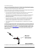
1.05 ERP/ π R
2
Where R is the distance to center (of any body part of person).
Solving for 10,000 mW @ 3ft. (91.44 cm) we get a power density of 0.4 mW per cm
2
.
The Yagi antenna in this scenario must be mounted in such a way that no body part of any person
may come closer than 3 feet in the direction of the main power beam. This will limit exposure to well
within the MPE.
Service antennas are also fixed mounted and covered by the same MPE considerations as the donor
antenna. However, this assumes that the area is always general population/uncontrolled and that the
minimum distance in most installations will be less than 3 feet. According to Table 1(B) of Section
1.1310, the power density @ 894 MHz is 0.596 mW/cm
2
. The maximum power of the 48900
downlink (base to service area) is +22 dBm (160 mW). Assuming no feeder cable loss and a service
area antenna gain of 8 dB, a safe minimum separation of 10 inches (25 cm) is required to stay within
the MPE.
1.05 x 1000 mW/3.14 x 252 = 1050/1962.5 =0.535 mW/cm
2
Therefore, the service area antenna should be mounted such that no body parts of any person may
come closer than 10 inches (or 25 cm). The service area antenna gain is 8 dB in the example above,
but may be increased to make up for cable and/or splitter or tap losses. For example, if a 2-way
splitter is used to provide for two antennas in different parts of the service area, then the antenna gain
may be increased to 11 dB to make up for the loss of the splitter 3.6 dB. The maximum service area
antenna gain for any specific location can be calculated as follows:
8dB+ accumulated losses to the antenna.
Product Overview
Field Tune-up, Alignment or Calibration
There is no field tune-up or calibration necessary. These units are aligned and calibrated at the time
of manufacture and are designed to retain calibration throughout the life of the product.
FCC ID and Canada Certification Numbers
The listed models have been tested and granted certification by the FCC in accordance with CFR
Title 47, Part 90 and by the DOC in accordance with RS 131, Issue 131.
The FCC identification number for each particular model appears on a label on the faceplate of the
unit. Applicable FCC identification and Canadian ISC numbers are as shown:
FCC ID Canada
IWD48900 TBD