
User Manual

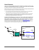
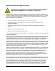
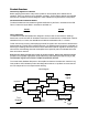
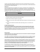
Table Of Contents

maximum gain. Manual attenuation is separate from the AGC so these attenuators can be used to
reduce overdrive while maintaining AGC range. At the full clockwise position, 20 dB of attenuation will
be introduced in the respective gain path.
AC/DC Power
AC power is supplied through a standard 3-wire male plug connected through a standard IEC-320
plug. Connect this plug to any standard 3-wire 120 VAC outlet. A 5x20 mm, .315 amp fast-blow fuse
is used to disconnect power in the event of a severe AC fault. A 5 amp mini ATO fuse is used
between the 5.5 VDC from the power supply and the control board, which distributes the power to all
components. This fuse is located on the control board.
DANGER
Always remove power before checking or changing fuses. 120VAC can be lethal.
⌦ Always unplug the amplifier before servicing the interior.
⌦ Never insert conductive objects into any opening.
⌦ Never remove or probe under the plastic safety shield covering the AC terminals of the power
supply.
⌦ Always use a standard 3-wire electrical outlet, with safety ground, for connection to AC
power.
Grounding and Surge Protection
The unit is case grounded through the three-prong plug. The donor antenna feeder cable should
have a cable ground attached to it, along with an inline surge arrestor between the donor antenna
and the 48810 “Base” port. The distribution network need not be grounded in building installations.
However, the distribution network in tunnels, subways or outdoor installations should also include a
cable ground and inline surge arrestor at or near the “Service” port.
Antenna Isolation
Isolation between the donor (base) antenna and service area antenna should be 20 dB greater
than the gain of the repeater amplifier.
If the isolation is less than the amplifier gain, then positive feedback sufficient for oscillation is present
in the system. Such oscillations will overdrive one or both amplifier chains and continuously activate
the AGC auto-shutdown circuitry. This situation will be apparent by the red fault LED being lit.
Antenna isolation is usually not a problem for in-building installations. Isolation is improved by using a
directive donor antenna and facing it away from the distribution or service antenna(s). Decoupling is
achieved by spatially separating the antennas vertically and/or horizontally. Other factors influencing
isolation include multi-path reflections, structures, other antennas, passing vehicles, personnel
proximity, etc. Contact RFS Applications Engineering for further assistance.
It is always best to measure the isolation before connecting the repeater. The most direct way to
measure the isolation is to inject a known signal into one antenna, and measure the coupled signal at
the other antenna. This should be done across the applicable bandwidth to account for the frequency
dependency of standing waves.
6