
User Manual

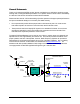
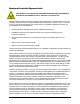
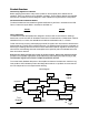
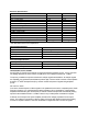
Table Of Contents

Electrical Specifications
Downlink Uplink
48810A, Block, selectable A, B, C A, B, C
48881B, Block, selectable D, E, F D, E, F
Gain, no attenuation 87 dB 87 dB
Gain Flatness, typical ±1.0 dB ±1.0 dB
Manual Attenuator Range 20 dB 20 dB
Output Limiter Range, Automatic* 20 dB 20 dB
Noise Figure, typical** 4.0 dB 4.0 dB
Composite Power, typical* +15 dBm +15 dBm
TDMA, CDMA, GSM
Impedance 50 Ohms 50 Ohms
VSWR, input 1.5 1.5
Propagation Delay, worst case at band edge <3.0 microseconds <3.0 microseconds
Power, 120/220 Auto Ranging, IEC-320 Socket 120 VAC@1.4A 120 VAC@1.4A
*AGC circuitry monitors the output power and reduces the gain to prevent overdrive and oscillation.
**No attenuation and at room temperature.
Mechanical Specifications
Connectors, RF N Female
Weight 33 lbs (14.9 kg)
Size, L x W x D 13 x 18.76 x 7.5 Inches (33.02 x 47.7 x 19.1 cm)
Mounting Centers 10.75 x 17.56 Inches (27.3 x 44.6 cm)
Diagnostics 15 Pin Dsub Connector
Environmental Specifications
Operating Temperature, ambient -30 to +50 °C
Maximum humidity 95% RH (non condensing)
Environmental Rating Similar to NEMA 3R
Intermodulation, Power, and AGC
Per CFR Title 47, Part 24, there shall be no spurious emissions greater than {43+ 10 Log 10 (Power
Out Watts)} dB below the carrier Power Out (dB) level. This is always equivalent to -13 dBm.
The primary contributor to spurious emissions is multiple signal intermodulation. As multiple signals
are amplified, they generate intermodulation products (IM). The level of IM is a factor of the amplifiers
linearity or 3
rd
Order Intercept Point (IP3), and the number and power of signals being amplified
(Pout).
IM = 3xPout - 2xIP3
‘Pout’ is the combined power of all the signals in the passband known as the composite power. Radio
Frequency Systems, Inc. has designed the 48810 repeaters using a combination of low distortion
amplifiers and automatic gain control (AGC) to achieve maximum output while automatically limiting
spurious intermodulation levels to -13 dBm or less for any number/power combination of signals.
A detector on the output of the power amplifier provides a DC voltage proportional to the output
power. This voltage is compared to a factory setting. As long as this voltage is less than the setting,
no action is required. However, when the combination of signal level and or number of signals
4