
User Manual

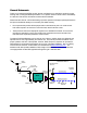
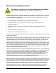
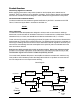
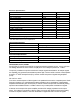
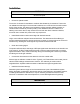
Table Of Contents

Product Overview
Field Tune-up, Alignment or Calibration
Before applying power set the rotary switch (located on the face plate) to the desired band of
operation. There is no field tune-up or calibration necessary. These units are aligned and calibrated
at the time of manufacture and are designed to retain calibration throughout the life of the product.
FCC ID and Canada Certification Numbers
The listed models have been tested and granted certification by the FCC in accordance with CFR
Title 47, Part 24 and by the DOC in accordance with RSS 131.
FCC ID
Canada
IWD48810 TBD
Theory of Operation
The 48810A and 48810B repeaters are designed to enhance radio communication in buildings,
basements, tunnels and other RF shielded environments. The 48810A has a 15 MHz band customer
selectable to A,B, or C block, the 48810B has a 5 MHz band selectable to D, E, or F block.
These units work by receiving and amplifying the base TX signals via a donor antenna directed at the
desired base site. This RF path is called the downlink. The amplified base TX signal is re-radiated via
antenna(s) or radiating cable into the Service Area. Subscriber mobile RF signals are received by the
same service area radiating elements and amplified in the uplink RF path to be radiated back to the
base via the donor antenna.
B
B
o
o
t
t
h
h
l
l
i
i
n
n
k
k
s
s
h
h
a
a
v
v
e
e
A
A
G
G
C
C
(
(
a
a
u
u
t
t
o
o
m
m
a
a
t
t
i
i
c
c
g
g
a
a
i
i
n
n
c
c
o
o
n
n
t
t
r
r
o
o
l
l
)
)
t
t
o
o
p
p
r
r
e
e
v
v
e
e
n
n
t
t
o
o
v
v
e
e
r
r
d
d
r
r
i
i
v
v
e
e
.
.
M
M
a
a
n
n
u
u
a
a
l
l
g
g
a
a
i
i
n
n
a
a
d
d
j
j
u
u
s
s
t
t
m
m
e
e
n
n
t
t
i
i
s
s
a
a
l
l
s
s
o
o
p
p
r
r
o
o
v
v
i
i
d
d
e
e
d
d
.
.
T
T
h
h
e
e
c
c
o
o
m
m
p
p
o
o
s
s
i
i
t
t
e
e
o
o
u
u
t
t
p
p
u
u
t
t
p
p
o
o
w
w
e
e
r
r
i
i
s
s
s
s
e
e
t
t
a
a
t
t
t
t
h
h
e
e
f
f
a
a
c
c
t
t
o
o
r
r
y
y
a
a
n
n
d
d
l
l
i
i
m
m
i
i
t
t
e
e
d
d
b
b
y
y
t
t
h
h
e
e
A
A
G
G
C
C
c
c
i
i
r
r
c
c
u
u
i
i
t
t
r
r
y
y
s
s
o
o
t
t
h
h
a
a
t
t
i
i
n
n
t
t
e
e
r
r
m
m
o
o
d
d
u
u
l
l
a
a
t
t
i
i
o
o
n
n
s
s
i
i
g
g
n
n
a
a
l
l
s
s
w
w
i
i
l
l
l
l
n
n
o
o
t
t
e
e
x
x
c
c
e
e
e
e
d
d
-
-
1
1
3
3
d
d
B
B
m
m
a
a
s
s
s
s
p
p
e
e
c
c
i
i
f
f
i
i
e
e
d
d
b
b
y
y
t
t
h
h
e
e
F
F
C
C
C
C
.
.
The control board distributes DC power to the amplifier modules and monitors each module for any
fault conditions. LED indicators provide visual diagnostics while the 15 pin Dsub connector has DC
and TTL test points for more in-depth trouble shooting.
Block Diagram
Duplexers
ServiceBase
Power Amplifier
LNA Converter
Power Amplifier
LNA Converter
Rx or
Uplink
Tx or
Downlink
Control Board
Test
Manual Gain
HF Filter
HF Filter
Power
and Fault
LEDs
Band
Select
3