
User Manual

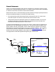
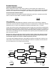
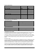
Table Of Contents

Maximum Permissible Exposure Limits
THIS PRODUCT IS CATEGORICALLY EXCLUDED FROM ROUTINE ENVIRONMENTAL
EVALUATION ACCORDING TO CFR 47, SECTION 1.1037 AND 2.1091.
Repeaters like the 48810 generate radio signals and thereby give rise to electromagnetic fields. The
installer is expected to have a complete understanding of CFR Title 47, Sections 1.1307, 1.1310 and
2.1091. A brief discussion follows but is not intended to be a substitute. Additional information can
also be obtained from OET Bulletin 65.
Antenna installation should be performed by qualified technicians only.
Installation instructions are not optional and are for the purpose of satisfying FCC RF
Exposure Compliance.
All antennas (donor and service) are to be fixed-mounted and physically secured to one
location.
Maximum donor antenna gain is 28 dB.
Maximum service area antenna gain is 10 dB.
There are two types of antennas attached to this unit. Installation considerations for both of these will
be discussed separately.
Donor antennas receive the base site TX signals and transmit the mobile TX signals back to the base
site (uplink paths). These are typically mounted on rooftops or tower structures in occupational /
controlled esposure areas. The maximum composite power of the uplink path is +15 dBm (32 mW).
Section 1.307(b)(1) excludes from routine environmental evaluation, facilities, operations and
transmitters that, according to Table 1 (titled "Cellular Radiotelephone Service"), are less than 1000W
ERP for building mounted antennas and less than 1000W and greater than 10 meters above ground
for non building-mounted antennas. As such, with maximum power from the uplink path @ +15 dBm
(32 mW) and a maximum antenna gain of 28 dB, the donor antenna installation will not exceed 20
Watts (+43 dBm) and is categorically excluded.
However, according to Section 1.1307 (b)(1), the appropriate exposure limits of 1.1310 are applicable
to all facilities, operations, and transmitters. Therefore, the MPE (Maximum Permissible Exposure) of
Section 1.1310 applies to the donor antenna installation. OET Bulletin 65 provides methods of
calculating power density based upon the ERP and distance. It would be impossible to cover every
possible configuration in this manual. Likewise, it would be unreasonable to dictate the exact
parameters of every installation; therefore, it is the responsibility of the qualified technician to know
and ensure that Sections 1.1307 and 1.1310 of CFR Title 47 are being met.
Service antennas are also fixed mounted and covered by the same MPE considerations as the donor
antenna. However, a more stringent method would be to consider these antennas in the worse case
as mobile devices mounted in the ceiling of a general population/uncontrolled exposure area with a
minimum separation of 20 cm. According to section 2.1091 routine evaluation is not required for
frequencies above 1500 MHz if the ERP is less then 3 watts. The maximum power of the 48810
downlink (base to service area) is +15 dBm (32 mW). Assuming an antenna gain of 10 dB, ERP
would be 25 dBm or .316 W. As such, the service area antennas are categorically excluded.
2