
User Manual
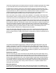
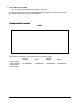

Table Of Contents

Mount repeater upright, with the connections toward the floor.
Ensure there is sufficient space above and below the unit to allow airflow through the heat sink.
Check to make sure the AC power cord can reach the power source. Also, provide adequate
bending radii for the coaxial cables.
Connect service antenna(s) to "Service Area" port via a 50-ohm coaxial cable.
Multiple service area antennas/radiating cable runs may be connected to the 48810. Splitters and
taps may be used to accommodate unique distribution systems.
Connect the donor antenna cable to "Base".
Connect the PM800-10 to the test port.
The PM800-10 performance monitor is provided with each unit. This monitor connects to the 15-
pin diagnostics Dsub connector on the bottom of the unit either directly or via the 10-foot
extension cable. The PM800-10 provides LED readouts of the pins as explained in the
diagnostics/troubleshooting section.
Select the desired band via the rotary switch on the faceplate.
Connect AC power to the unit and observe. See troubleshooting section.
Test the installation.
This test should include multiple subscribers in various locations of the service area. It should
also include one subscriber in fairly close proximity to the service antenna. This test will check to
ensure that a nearby user does not overdrive the uplink and reduce coverage for the other users.
See the troubleshooting guide if there is an overdrive condition in either the uplink or downlink.
Diagnostics/Troubleshooting
LED’s located in 487XX faceplate
Problem: Solution:
Green power LED not lit.
Check power source and the AC fuse located in the EIC plug.
Check for DC voltage (see below).
Green power LED lit and no red Fault
LED, unit does not appear to be
working.
Check for a break in the donor or distribution networks. First,
check both RF output via the DC voltages on Pins 12 and 13
or UL DET.V and DL DET.V from the PM800-10. Also, check
to ensure the donor signal is still available to the repeater. An
obstruction could be blocking the donor base site or the donor
antenna could have become misaligned. Then, check the
integrity of the distribution network. Coaxial cable has a
minimum bending radius, if that is exceeded the inner
conductor may crack or break causing excessive reflections to
the signals.
Red LED is lit.
The red LED indicates a summary fault from any of the fault
conditions identified in the Test Points section. Specific action
is described in that section.
8