48810A & 48810B User's Manual 200 Pondview Drive, Meriden, CT 06450 • (877) 737-9675 • Fax (203) 821-3852 www.rfsworld.
Disclaimer All information and statements contained herein are accurate to the best of the knowledge of Radio Frequency Systems, but Radio Frequency Systems does not make any warranty with respect thereto, including without limitation any results, which may be obtained from the products described herein or the infringement by such products of any proprietary rights of any persons.
Table of Contents General Statements 1 Maximum Permissible Exposure Limits 2 Product Overview 3 Field Tune-up, Alignment or Calibration 3 FCC ID and Canada Certification Numbers 3 Theory of Operation 3 Electrical Specifications 4 Mechanical Specifications 4 Environmental Specifications 4 Intermodulation, Power, and AGC 4 AGC Automatic Shutdown 5 Manual Gain Adjustment 5 AC/DC Power 6 Grounding and Surge Protection 6 Antenna Isolation 6 Installation 7 Diagnostics/Troubleshooti
General Statements Thank you for selecting this RFS product. We are confident that you will find this product in proper working order, meeting all stated specifications. If not, please contact customer service immediately at 1-800-321-4700 and we will resolve the issue without hesitation. Please read this manual. A full understanding of product operation will support optimal performance and prevent accidental damage not covered by the stated warranty.
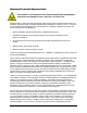
Maximum Permissible Exposure Limits THIS PRODUCT IS CATEGORICALLY EXCLUDED FROM ROUTINE ENVIRONMENTAL EVALUATION ACCORDING TO CFR 47, SECTION 1.1037 AND 2.1091. Repeaters like the 48810 generate radio signals and thereby give rise to electromagnetic fields. The installer is expected to have a complete understanding of CFR Title 47, Sections 1.1307, 1.1310 and 2.1091. A brief discussion follows but is not intended to be a substitute. Additional information can also be obtained from OET Bulletin 65.
Product Overview Field Tune-up, Alignment or Calibration Before applying power set the rotary switch (located on the face plate) to the desired band of operation. There is no field tune-up or calibration necessary. These units are aligned and calibrated at the time of manufacture and are designed to retain calibration throughout the life of the product.
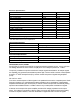
Electrical Specifications 48810A, Block, selectable 48881B, Block, selectable Gain, no attenuation Gain Flatness, typical Manual Attenuator Range Output Limiter Range, Automatic* Noise Figure, typical** Composite Power, typical* TDMA, CDMA, GSM Impedance VSWR, input Propagation Delay, worst case at band edge Power, 120/220 Auto Ranging, IEC-320 Socket Downlink A, B, C D, E, F 87 dB ±1.0 dB 20 dB 20 dB 4.0 dB +15 dBm Uplink A, B, C D, E, F 87 dB ±1.0 dB 20 dB 20 dB 4.0 dB +15 dBm 50 Ohms 1.5 <3.
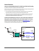
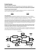
causes the composite power to exceed the safe level, the AGC's comparator generates a DC voltage to a pin diode attenuator that increases attenuation in proportion to the level of the DC voltage. The attenuation reduces the output power until the detector voltage is at a safe level again. If the number or power of the signals is reduced, the DC offset voltage will reduce the level of attenuation. In typical operation, the AGC is only active when needed to prevent overdrive.
maximum gain. Manual attenuation is separate from the AGC so these attenuators can be used to reduce overdrive while maintaining AGC range. At the full clockwise position, 20 dB of attenuation will be introduced in the respective gain path. AC/DC Power AC power is supplied through a standard 3-wire male plug connected through a standard IEC-320 plug. Connect this plug to any standard 3-wire 120 VAC outlet. A 5x20 mm, .315 amp fast-blow fuse is used to disconnect power in the event of a severe AC fault.
Installation WARNING Do not connect AC power until antennas have been connected to both the base and service area ports. Choose an optimal location. The choice of a location for the 48810 to reside is often dictated by circumstance. These units can withstand a wide range of environmental conditions, but a cooler environment will increase the life of the product. The 48810 is not intended for outdoor operation without protection. A central location is desired to provide symmetry in the distribution network.
Mount repeater upright, with the connections toward the floor. Ensure there is sufficient space above and below the unit to allow airflow through the heat sink. Check to make sure the AC power cord can reach the power source. Also, provide adequate bending radii for the coaxial cables. Connect service antenna(s) to "Service Area" port via a 50-ohm coaxial cable. Multiple service area antennas/radiating cable runs may be connected to the 48810.
Yellow AGC LED is lit. Flashing Red Fault LED Checking DC Voltage AGC LEDs indicate an overdrive condition in the respective link. Reduce the respective link gain via the Gain Adjust until the LED goes out. Generally, the opposing link gain should be adjusted to approximately the same setting. If the LED does not go out, then the input signal is too strong and should be attenuated with a 10 dB in-line attenuation pad on the Base or Service port.
Pin 8 indicates that the unit is in automatic shutdown mode due to an overdrive that is exceeding the AGC’s range. The AGC is non-latching and will clear itself when the overdrive is removed. The alarm light will remain lit even though the shut down feature is powering on and off to check for the overdrive condition.
Pin 15: Max source = 80mA. Pin 15: +5VDC, thermally fused (self resetting), 50mA max. Pin 15 can be used as the drive voltage to disable the unit using Pin 9. It is also used to power the PM800-10 performance monitor, when attached.
Maintenance, Repair and Warranty Periodic Maintenance There is no periodic maintenance required for the 48710 or 48722. As long as the repeaters are kept away from extreme temperatures and moisture, they should provide long-term, carefree operation. However, as a system, periodically check all RF connections for corrosion, strain damage, and proper tightness. Also, periodically check the AC power connections for integrity.