
User Manual

ITEM # 602100022500
DOCUMENT TYPE:
Operation and Installation Manual
REV: 0
DOC #:
602100022500
PAGE 9 OF 17
TITLE:
Bi-Directional Amplifier System
Intermodulation, Power, and AGC
FCC requires that spurious emissions be less than {43+ 10 Log 10 (Power Out Watts)} dB below the
carrier Power Out (dB) level. This is always equivalent to -13 dBm. The primary contributor to
spurious emissions is multiple signal intermodulation. As multiple signals are amplified, they generate
intermodulation products (IM). The level of IM is a factor of the amplifiers linearity or 3
rd
Order
Intercept Point (IP3), and the number and power of signals being amplified (Pout).
IM = 3xPout - 2xIP3
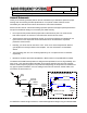
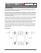
The 48700 signal boosters use a combination of low distortion amplifiers and automatic gain control
(AGC) to achieve maximum output while automatically limiting spurious intermodulation levels to -13
dBm. A detector on the output of the amplifier provides a DC voltage proportional to the output
power. This voltage is compared to a factory setting. As long as this voltage is less than the setting,
no action is required. However, when the combination of signal level and or number of signals
causes the composite power to exceed the safe level, the AGC's comparator generates a DC voltage
to a pin diode attenuator that increases attenuation in proportion to the level of the DC voltage.
The attenuation reduces the output power until the detector voltage is at a safe level again. If the
number or power of the signals is reduced, the DC offset voltage will reduce the level of attenuation.
In typical operation, the AGC is only active when needed to prevent overdrive. If the AGC is
constantly activating, RFS suggests that you reduce the gain via the manual attenuator and verify
that an oscillation between the base and service antenna systems does not exist.
AGC in the uplink is rarely needed in modern radio installations. As a portable comes closer to the
internal antenna network, its signal becomes stronger at the base site. Typically, the dynamic power
control at the base will turn the portable's power down to reduce interference and conserve power.
Overdrive is more likely to occur on the downlink path. All active signals at the donor base site will be
amplified by the repeater regardless of whether or not they are in use in the service area. Ideally, the
donor antenna is directional. This limits the number of donor base sites the repeater recognizes and
reduces the potential for interference. RFS recommends that you observe the signal levels before
connecting the repeater. Out of band signals can also cause overdrive. The most likely cause of an
overdrive condition is oscillation from inadequate antenna isolation.
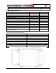
Table 1 lists the typical output power per signal, which can be expected from the 48760 for a given
number of active signals operating at equal input levels. For a donor site that has 16 signals, the full
power per signal would be +11 dBm, assuming the incoming signal is sufficient so that that level will
be achieved.
Number of signals dBm mW
1 27.0 500
2 23.0 200
4 19.0 80
8 15.0 32
16 11.0 13
32 7.0 5
TABLE 1: TYPICAL OUTPUT POWER PER SIGNAL