
User Manual

ITEM # 602100022500
DOCUMENT TYPE:
Operation and Installation Manual
REV: 0
DOC #:
602100022500
PAGE 7 OF 17
TITLE:
Bi-Directional Amplifier System
Theory of Operation
The 48760 BDA is designed to enhance radio communication in buildings; basements, tunnels and
other RF shielded environments. The 48760 is a dual band BDA that will amplify both the 800 and
900 SMR as listed in the electrical specifications.
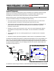
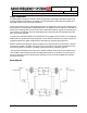
These units work by receiving and amplifying the base TX signals via a donor antenna directed at the
desired base site. This RF path is called the downlink. The amplified base TX signal is re-radiated via
antenna(s) or radiating cable into the Service Area. Subscriber mobile RF signals are received by the
same service area radiating elements and amplified in the uplink RF path to be radiated back to the
base via the donor antenna.
The uplink and downlink amplifiers are broadband to accommodate all the channels in the passband.
Differentiation is provided by the duplexing filters. These determine the basic pass band and prevent
oscillation between the uplink and downlink by attenuating the opposing link frequencies.
Both the downlink and uplink gain paths have Manual and Automatic Gain Control (AGC) to prevent
an overdrive condition. The AGC set point is factory set so that the output of the link will not exceed
FCC limits for spurious emissions (-13 dBm). Further discussion is provided in page 10.
The control board distributes DC power to the amplifier modules and monitors each module for any
fault conditions. LED indicators provide visual diagnostics while the 15 pin Dsub connector has DC
and TTL test points for more in-depth trouble shooting. Each unit includes a PM800-10 hand held
performance monitor.
Block Diagram