
User Manual

ITEM # 602100022500
DOCUMENT TYPE:
Operation and Installation Manual
REV: 0
DOC #:
602100022500
PAGE 16 OF 17
TITLE:
Bi-Directional Amplifier System
Pins 12 and 13 are detector output voltages for the associated path. The DC voltage represents
the output power. These voltages can be used to roughly estimate the amount of output power.
For example, the donor antenna can be rotated to look for maximum output power if a spectrum
analyzer is not available.
Pin 14: Max sink = 1A.
14. Ground for Pins 10-13.
Pin 15: Max source = 80mA.
Pin 15: +5VDC, thermally fused (self resetting), 50mA max.
Pin 15 can be used as the drive voltage to disable the unit using Pin 9. It is also used to power
the performance monitor, when attached.
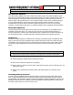
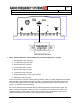
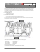
Component Location
Field repair for the 48760 is recommended only for the following parts:
Power Supply 315300001900
Pre-Amp Stage: LNA80-0002A
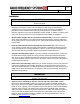
Power Amplifier: PA80-9942A
Recommended Spare, per 4 units:
1 PA80-9942A Power Amplifier, 1 315300001900 Power Supply
LNA80-0002A
PA80-9942A