
User Manual

ITEM # 602100022500
DOCUMENT TYPE:
Operation and Installation Manual
REV: 0
DOC #:
602100022500
PAGE 15 OF 17
TITLE:
Bi-Directional Amplifier System
Pin 8 indicates that the unit is in automatic shutdown mode due to an overdrive that is
exceeding the AGC’s range. The AGC is non-latching and will clear itself when the overdrive is
removed. The alarm light will remain lit even though the shut down feature is powering on and
off to check for the overdrive condition.
Conditions that can cause AGC to reach its limit include the presence of one or more very strong
channels, a strong in-band noise source, or amplifier oscillation due to inadequate antenna isolation.
Disconnect the power and the Base and Service cables. Use a spectrum analyzer to look for strong
input signals coming from the base donor antenna or the service area distribution network. If there
are no strong input signals, check the antenna isolation as described in this manual. Reducing the
gain may also help to clear the condition. See AGC section for more information.
Strong uplink signals may be intermittent. These may be present when a mobile in the coverage area
is close in to the service area antenna. In this case, the service area antenna must be moved to
prevent overdrive under normal operating circumstances.
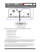
Pin 9: Max sink = 7uA. Max input = 6.0 VDC
Pin 9 is a remote disable feature. Connecting pin 15 to pin 9 via a relay will cause the repeater to
shut down. This can be accomplished with a remote control unit like the RPM800 (remote
performance monitor).
9. Disable (input), logic, high=disable
Pins 10-13: Max sink = 8mA. Max source = 15mA.
10. Rx AGC Voltage, analog, no AGC approximately 26.5 VDC, Full AGC approximately 7.65
VDC
11. Tx AGC Voltage, analog, no AGC approximately 26.5 VDC, Full AGC approximately 7.65
VDC
12. Rx Det. Voltage, analog, approximately 0 to 3VDC @ approximately 0.3VDC per dB
13. Tx Det. Voltage, analog, approximately 0 to 3VDC @ approximately 0.3VDC per dB
Pins10 and 11 are the indicators for Automatic Gain Control. Please see the section on AGC in
this manual for more information. The circuitry is housed in the PA amplifier stage. It monitors the
output power and controls a pin attenuator to reduce gain and thus, the output power if needed to
prevent overdrive. The DC voltages on pins 10 and 11 represent the amount of attenuation:
No AGC approx. 26.5VDC, full AGC approx. 7.65VDC. The yellow LEDs light up when the AGC
is active (adding attenuation).
AGC may be intermittent due to temporary overdrive conditions. If the LED is constantly lit then
reducing the manual gain via adjustment on the faceplate should cause the LED to go out. The
manual attenuator is separate from the AGC attenuator. Reducing the gain via the manual
attenuator will optimize the installation and preserve the full AGC attenuation for overdrive
conditions.