
User Manual

ITEM # 602100022500
DOCUMENT TYPE:
Operation and Installation Manual
REV: 0
DOC #:
602100022500
PAGE 13 OF 17
TITLE:
Bi-Directional Amplifier System
Diagnostics/Troubleshooting
Problem: Solution:
Green power LED on faceplate not lit.
Check power source and the AC fuse located in the EIC plug.
Check for DC voltage (see below).
Green power LED lit and no red Fault
LED on faceplate; unit does not
appear to be working.
Check for a break in the donor or distribution networks. First,
check both RF output via the DC voltages on Pins 12 and 13
or RxDET.V and TxDET.V from the performance monitor.
Also, check to ensure the donor signal is still available to the
repeater. An obstruction could be blocking the donor base site
or the donor antenna could have become misaligned. Then,
check the integrity of the distribution network. Coaxial cable
has a minimum bending radius, if that is exceeded the inner
conductor may crack or break causing excessive reflections to
the signals.
Yellow AGC LED on performance
monitor is lit.
AGC LEDs indicate an overdrive condition in the respective
link. Reduce the respective link gain via the Gain Adjust until
the LED goes out. Generally, the opposing link gain should be
adjusted to approximately the same setting. If the LED does
not go out, then the input signal is too strong and should be
attenuated with a 10 dB in-line attenuation pad on the Base or
Service port.
Red LED on faceplate is lit.
The red LED indicates a summary fault from any of the fault
conditions identified in the Test Points section. Specific action
is described in that section.
Checking DC Voltage
DC Voltage can be checked via the 15-pin test port. Pins 10
and 11 are the DC voltage associated with the AGC circuitry.
There should be at least 7 volts to ground-pin 14. Alternatively,
you can plug in the performance monitor into the test port and
measure the Rx AGCV to ground.
Test Point Descriptions
The performance monitor is included with all 487XX series Band Specific Repeaters and is designed
to provide convenient visual readout. A DC VOM can be used to quickly assess the health of the unit.
The 487XX provides the output voltages and the power to operate the performance monitor. The
monitor includes a 10-foot extension. A 30-foot extension cable (part #: 103300014900) is also
available for remote mounting or the monitor can be directly plugged into the 15-pin test port located
on the front plate of any 487XX series. Should the performance monitor become damaged, contact
RFS customer service at 1-800-321-4700 to order a replacement.
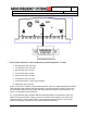
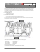
In the following performance monitor description, the term “pin number” refers to the connector pins
in the bottom of the 487XX series or the associated performance monitor LED indicators. Pin
numbering starts upper right and proceed from right to left, top to bottom when viewed externally, as
seen below. The functions are explained below with details on how the unit is used in practical
applications.