
User Manual

ITEM # 602100022500
DOCUMENT TYPE:
Operation and Installation Manual
REV: 0
DOC #:
602100022500
PAGE 12 OF 17
TITLE:
Bi-Directional Amplifier System
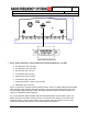
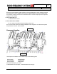
Connect the service area antennas to the “Service” port.
Connect the donor antenna cable to "Base" port.
Connect AC power to the unit and observe power and fault LEDs
Ideally, a spectrum analyzer should be used to confirm the DL signal at the service port.
However, the 48760 has diagnostics to assist with optimization as discussed below.
Confirm the green “PWR” LEDs are lit in both the uplink (UL) and downlink (DL) and that the red
“Fault” LED is not lit. Connect the PM800-10 to the test port via cable provided. If there is a red
fault LED lit, check the trouble shooting section for details. If the yellow DL AGC LED is lit then it
is suggested to reduce the gain in the DL via the manual attenuator. Turn the adjustment
clockwise to reduce gain until the AGC LED goes out. Then adjust the UL gain to the same
setting to minimize noise generated in the uplink and balance the links.
If both LEDs are lit then there is likely an oscillation between the antennas – see “Antenna
Isolation”. Also read the section on “Intermodulation, Power, and AGC”
Test the coverage.
Ideally, this test should include multiple subscribers in various locations of the service area with
one subscriber in close proximity to the 48760. This will check to ensure that a nearby subscriber
does not overdrive the uplink and reduce coverage for the other users.
If the UL AGC LED lights during the system test it most likely indicates that there is a hot spot in
the service area, where the subscriber signal is overdriving the uplink. It is best to minimize this
effect by relocating the nearest service antenna or adding an attenuator pad to reduce the UL
signal strength at the offending antenna. In some cases, a coupler may be needed to add a low
power antenna in specific locations. For this reason it is best to have extra antennas, splitters,
couplers and coax.
Antenna Isolation
Isolation between the donor (base) antenna and service area antenna should be 20 dB greater
than the gain of the repeater amplifier.
If the isolation is less than the amplifier gain, then positive feedback sufficient for oscillation is present
in the system. Such oscillations will overdrive one or both amplifier links and may continuously
activate the AGC auto-shutdown circuitry.
Antenna isolation is usually not a problem for in-building installations. Isolation is improved by using a
directive donor antenna and facing it away from the distribution or service antenna(s). Decoupling is
achieved by spatially separating the antennas vertically and/or horizontally. Other factors influencing
isolation include multi-path reflections, structures, other antennas, passing vehicles, personnel
proximity, etc.
It is always best to measure the isolation before connecting the 48760. The most direct way to
measure the isolation is to inject a known signal into one antenna, and measure the coupled
signal at the other antenna. This should be done across the applicable bandwidth to account for
the frequency dependency of standing waves.