
User's Manual
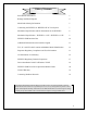
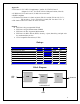
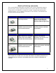
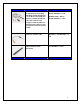
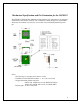
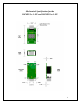
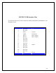
Table Of Contents
- Table of Contents
- Features
- Ratings
- Block Diagram
- Model and Ordering Information
- Model
- Description
- Comments
- WiFiHU2-a
- WiFi USB Module with dual on board chip antennae
- Uses onboard chip antennae. Not for use with External Antenna. Allows designer to determine USB Jack placement.
- WiFiHU2-a-1-NE
- WiFiHU2-a installed in a WiFiHU2-CB1 Carrier Board with on board USB Jack.
- Complete WiFi Module with dual chip antennae with USB Jack interface.
- WiFiHU2-c *
- WiFi USB Module with two SMD Connectors for attaching antenna cables and 2.4GHz 2 dBi Omni-directional antennas
- Allows designer to determine USB Jack and antenna placement. Can use one or two cables and antennas
- WiFiHU2-c-1-NE*
- WiFiHU2-c installed in WiFiHU2-CB1 Carrier Board with on board USB Jack.
- Complete WiFi Module for 2 cables and 2 antennas with USB Jack interface.
- *These models can use either one or two cables and antennas. For ultimate performance, we recommend using two antennas to meet MIMO requirement with better adaptability for receiving.
- WiMDK-2001
- WiMDK-2001-a Kit for
- Model WiFiHU2-a-1-NE
- WiMDK-2001-c Kit for Model WiFiHU2-c-1-NE
- AC6i-RP-SMA
- 6" U.FL. to RP-SMA female connector antenna cable
- Antenna Cable for models WiFiHU2-c and WiFiHU2-c-1-NE
- ATN-2d-RP-SMA
- Replacement antenna, 2.4GHz, 2dBi, RP-SMA, Omni-directional.
- Antenna for models WiFiHU2-c and WiFiHU2-c-1-NE
- Connecting the WiFiHU2 or WiFiHU2-NE to Your System
- Mechanical Specification and Pin Orientation for the WiFiHU2
- Mechanical Specification for the
- WiFiHU2-c-1-NE and WiFiHU2-a-1-NE
- WiFiHU2 USB Interface Pins
- Additional Information on the Interface Signals
- Important Regulatory Compliance and User Information
- _
- FCC RF Radiation Exposure Statement
- IMPORTANT NOTE: To comply with the FCC RF exposure compliance requirements, the antenna used on this transmitter must be installed to provide a separation of at least 20 cm from all persons and must not be co-located or operating in conjunction with any antenna or transmitter. This device contains a low power transmitter. When this device is operational, use only with the supplied, or recommended antenna. Unauthorized antenna, modification, or attachments could damage the transmitter and may violate FCC regulations. Changes or modifications not expressly approved by the manufacturer or party responsible for compliance could void the user’s authority to operate the equipment.
- FCC Interference Statement
- This device complies with Part 15 of the FCC Rules. Operation is subject to the following conditions:
- (1) This device may not cause harmful interference
- (2) This device must accept any interference received, including interference
- that may cause undesired operation.
- This equipment has been tested and found to comply with the limits for a Class B digital device, pursuant to Part 15 of the FCC Rules. These limits are designed to provide reasonable protection against harmful interference in a residential installation.
- This equipment generates and radiates radio frequency energy and, if not installed and used in accordance with the instructions, may cause harmful interference to radio communications. There is no guarantee that interference will not occur in a particular installation. If this equipment does cause harmful interference to radio or television reception, which can be determined by turning the equipment off and on, the user is encouraged to try to correct the interference by one of the following measures:
- ● Reorient or relocate the receiving antenna.
- ● Increase the separation between the equipment and receiver.
- ● Connect the equipment into an outlet on a circuit different from that to which the receiver is connected.
- ● Consult the dealer or an experienced radio/TV technician for assistance.
- IC (Industry Canada) Statement
- This product meets the applicable Industry Canada technical specifications. / Le present materiel est conforme aux specifications techniques applicables d’Industrie Canada.
- Europe – R&TTE Compliance Statement:
- Hereby, Radicom Research Inc., declares that this equipment complies with the essential requirements and other relevant provisions of DIRECTIVE 1999/5/CE OF THE EUROPEAN PARLIAMENT AND THE COUNCIL of March 9, 1999 on radio equipment and telecommunication terminal Equipment and the mutual recognition of their conformity (R&TTE).
- CE Declaration of Conformity
- _
- For the following equipment:
- is herewith confirmed to comply with the requirements set out in the Council (European parliament) Directive on the Approximation of the Laws of the
- Member States relating to Electromagnetic Compatibility of Radio and Telecom device (1999/5/CE). For the evaluation regarding this Directive, the following
- standards were applied:
- EN 61000-3-2:2006+A2:2009, EN 300 328 V1.7.1, EN 62311: 2008,
- EN 301 489-1, V1.8.1, EN 61000-3-3:2008, EN 301 489-17 V2.1.1
- ________________________
- This equipment is marked with the and can be used throughout the European community.
- France – 2.4GHz for Metropolitan France:
- In all Metropolitan departments, wireless LAN frequencies can be used under the following conditions, either for public or private use:
- Indoor use: maximum power (EIRP*) of 100 mW for the entire 2400-2483.5 MHz frequency band
- Driver Installation Guide For Windows XP
- WiFiHU2 USB Linux Driver Quick Installation Guide
- Limited Warranty
- Contacting Radicom Research
- http://www.radi.com/

Connecting the WiFiHU2 or WiFiHU2-NE to Your System
rior to connecting the WiFiHU2 to a Window XP, the drivers should be installed. The
iFiHU2 Modules are designed for easy connection to any standard USB Port and
even
E
ounted onto a USB hub PCB (WiFiHU2-NE). To remove the
y
ance, we recommend using two antennas to meet MIMO
st
sest
P
W
wireless network. Connect one end of the USB cable into the USB connector on the
WiFiHU2-NE and the other into any available USB receptacle on your computer. The
WiFiHU2-NE’s “Hot Swap-able” interface allows you to plug or unplug the module
when the computer is on. If using Windows, load the provided drivers. The WiFiHU2-N
is now ready for use.
If you plan to embed the WiFiHU2 into your system, the initial evaluation consists of the
iFiHU2 USB Module mW
WiFiHU2 carefully remove it from the two 8 pin headers on the WiFiHU2-NE USB
interface board. Save this interface board. The WiFiHU2 can always be reinstalled into
the WiFiHU2-NE USB interface board and connected to any standard USB port to verif
or test the module functions.
If you use external antenna, connect one end of Radicom approved antenna to the on
oard socket. For ultimate performb
requirement with
exceptional reception and throughput. If only using one antenna, you mu
use the correct antenna socket for good performance. Connect single antenna to the socket clo
to the Radicom Research white silkscreen legend on the PCB.
7