
User's Manual
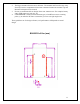
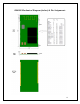
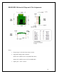
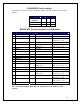
Table Of Contents
- Table of Contents
- Important Regulatory Compliance and User Information 8
- Introduction
- Features
- Model and Ordering Information
- Important Regulatory Compliance and User Information
- This equipment complies with FCC radiation exposure limits set forth for an uncontrolled environment. End users must follow the specific operating instructions for satisfying RF Exposure compliance. The end user should NOT be provided any instructions on how to remove or install the device. The users manual for end users must include the following information in a prominent location
- FCC RF Radiation Exposure Statement
- IMPORTANT NOTE: To comply with the FCC RF exposure compliance requirements, this device must not be co-located or operating in conjunction with any antenna or transmitter. This device contains a low power transmitter. When this device is operational, use only with the supplied, or recommended antenna. Unauthorized antenna, modification, or attachments could damage the transmitter and may violate FCC regulations. Changes or modifications not expressly approved by the manufacturer or party responsible for compliance could void the user’s authority to operate the equipment.
- FCC Interference Statement
- This device complies with Part 15 of the FCC Rules. Operation is subject to the following conditions:
- (1) This device may not cause harmful interference
- (2) This device must accept any interference received, including interference
- that may cause undesired operation.
- This equipment has been tested and found to comply with the limits for a Class B digital device, pursuant to Part 15 of the FCC Rules. These limits are designed to provide reasonable protection against harmful interference in a residential installation.
- This equipment generates and radiates radio frequency energy and, if not installed and used in accordance with the instructions, may cause harmful interference to radio communications. There is no guarantee that interference will not occur in a particular installation. If this equipment does cause harmful interference to radio or television reception, which can be determined by turning the equipment off and on, the user is encouraged to try to correct the interference by one of the following measures:
- ● Reorient or relocate the receiving antenna.
- ● Increase the separation between the equipment and receiver.
- ● Connect the equipment into an outlet on a circuit different from that to which the receiver is connected.
- ● Consult the dealer or an experienced radio/TV technician for assistance.
- IC (Industry Canada) Statement:
- “This device complies with Industry Canada license-exempt RSS standard(s). Operation is subject to the following two conditions: (1) this device may not cause interference, and (2) this device must accept any interference, including interference that may cause undesired operation of the device”
- Le present appareil est conforme aux CNR d’Industrie Canada applicables aux appareils radio exempts de license. L’exploitation est autorisee aux deux conditions suivantes: (1) l’appareil ne doit pas produire de brouillage, et (2) l’utilisateur de l’appareil doit acceptor tout brouillage radioelectrique subi, meme si le brouillage est susceptible d’en compromettre le fonctionnement.
- CE Declaration of Conformity
- _
- For the following equipment:
- are herewith confirmed to comply with the requirements set out in the Council (European parliament) Directive on the Approximation of the Laws of the
- Member States relating to Electromagnetic Compatibility of Radio and Telecom device (1999/5/CE). For the evaluation regarding this Directive, the following
- standards were applied:
- EN 61000-3-2:2006+A2:2009, EN 300 328 V1.7.1, EN 62311: 2008,
- EN 301 489-1, V1.8.1, EN 61000-3-3:2008, EN 301 489-17 V2.1.1
- ________________________
- This equipment is marked with the and can be used throughout the European community.
- France – 2.4GHz for Metropolitan France:
- In all Metropolitan departments, wireless LAN frequencies can be used under the following conditions, either for public or private use:
- Indoor use: maximum power (EIRP*) of 100 mW for the entire 2400-2483.5 MHz frequency band
- Europe – R&TTE Compliance Statement:
- Hereby, Radicom Research Inc. declares that this equipment complies with the essential requirements and other relevant provisions of DIRECTIVE 1999/5/CE OF THE EUROPEAN PARLIAMENT AND THE COUNCIL of March 9, 1999 on radio equipment and telecommunication terminal Equipment and the mutual recognition of their conformity (R&TTE).
- RB4000 Mechanical Diagram (inches) & Pin Assignments
- RB4000MB Carrier Board RS232 DB 9 Pin Definitions
- LED Operation
- Connecting to Your System
- Contacting Radicom Research
- http://www.radi.com/

Connecting to Your System
NOTE: Do Not Plug in the USB cable and AC power adapter at the
same time. Only use one or the other. Plugging in both the USB cable and AC power
adapter may damage the USB port on your PC or USB device.
Below is a simple example to show how the Radicom Bluetooth modules work. This
example demonstrates how the Bluetooth Modules can connect to each other.
1. RB4000MB-SPP-A Initiator setup: Open HyperTerminal and select an available
Serial Comport. Set the DTE speed to 115200bps, 8 Data bit, No Parity bit, One
Stop bit and No Flow control.
2. Connect one end of the RS232 Null modem cable (DB9 Female to DB9 Female)
to the Serial Comport and the other end of the cable to the RB4000MB-SPP-A
3. Apply power using either a USB cable or Optionally provided AC power adapter
to RB4000MB-SPP-A. The modules Firmware message should show up on the
HyperTerminal screen and the LED on the RB4000MB-SPP-A should be ON.
4. RB4000MB-SPP-B setup: Open HyperTerminal and select an available Serial
Comport. Set the DTE speed to 115200bps, 8 Data bit, No Parity bit, One Stop bit
and No Flow control.
5. Connect one end of the RS232 Null modem cable (DB9 Female to DB9 Female)
to the Serial Comport and the other end of the cable to the RB4000MB-SPP-B.
6. Apply power using either a USB cable or Optionally provided AC power adapter
to RB4000MB-SPP-A. The modules Firmware message should show up on the
HyperTerminal screen and the LED on the RB4000MB-SPP-B then start blinking.
7. When both Modules are powered-up, they should automatically connect to each
other as long as the modules are within acceptable distance, for example, 10m in
home or office).
8. The on board LEDs will show the modules Connect Status.
Note(s): They further apart the modules are, the longer it may take to connect and the
slower the data transfers will be. If the modules do not connect make sure that the
firmware displayed reflects that one module contains Initiator firmware and the other
module contains Acceptor firmware. For example, the Initiator should display SPP-B
XXX and the Acceptor should display SPP-A XXX where XXX is the firmware version.
17
Note: When Connected and no data activity, the modules will enter lower power Sniff
Mode after 5 to 7 seconds of inactivity. Any transmitted or received data will cause the
module to exit Sniff Mode and resume normal operation.