
Technical data


INSTALLATION
INSTRUCTIONS
_
CONDENSING WALL-HUNG BOILER – TG05A052.A0205
16
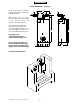
MINIMUM DISTANCE mm.
450
60 450 60
S
A
G
F
C
R
BOILER INSTALLATION MINIMUM DISTANCES FOR FIXING TO WALL
To allow access in the boiler for maintenance
operations, the minimum distances shown below
must be respected (fig. 1):
To facilitate installation, the boiler is supplied with a
template for advance location of connections to pipes.
In this way, you may simply hook up the boiler when
wall work is completed.
Installation Instruction
a) with a spirit level, draw a line on the wall on which
the boiler will be installed (fig. 2);
b) position the top of the template on the line drawn
with the spirit level (respecting the distances – see
fig. 1) than mark the three points for insertion of
the 3 screw anchors or wall anchors for fixing the
boiler hanging bracket (choose proper anchors
according to the wall type);
c) fix the hanging bracket
d)
make connections to the hot and cold water
supply, to the gas pipe and to the heating system
with the fittings. Connect pipes and valves as
shown in the picture;
e) position the boiler paying attention to hang it to the
hanging bracket and make final connections;
WATER CONNECTIONS
To facilitate installation, the boiler is equipped with a
fittings kit (fig. 3).
IMPORTANT:
Before connecting the heating system pipes, carefully
clean the system to prevent residual dirt from entering
into circulation and negatively affecting boiler
function. Install a funnel with discharge under the
safety valve (calibrated to 3 bar) to collect water in
case of leaking due to overpressure. No safety valve
is needed for the domestic water circuit, but be sure
that pressure does not exceed 6 bar.
• avoid using pipelines of reduced diameter;
• avoid the use of tight bends and adapters in
important sections;
• clean out the system thoroughly before connecting
up the boiler in order to eliminate any residue left
in the pipes and radiators;
N.B.: Make sure that the water and heating pipes are
not used as earth connections for electrical
apparatus.
Fig. 2
Fig. 1
FITTINGS KIT
Fig. 3
R HEATING RETURN ¾”
G GAS ½”
C HOT WATER ½”
F COLD WATER ½”
A
HEATING FLOW ¾”