Instruction Manual for models RKA 25 Premix condensing boiler with storage cylinder SEDBUK BAND A GAS COUNCIL NUMBER: 47-651-21 Installation, operating, commissioning and maintenance instructions. CE 0694 Documentazione Tecnica RADIANT BRUCIATORI S.p.A. Montelabbate (PU) ITALY TG05A095.
CONTENTS 1. General information 1.1 General Installation Information page 1 1.2 Product conformity page 3 2. Technical characteristics 2.1 Technical data page 4 2.2 Dimensions page 5 2.3 Internal parts of the boiler page 6 2.4 Water circuit page 7 2.5 Circulation pump head graph page 8 2.6 Printed circuit board page 9 2.7 Control panel page 10 3. Installing the appliance (authorised personnel) 3.1 Reference standard page 11 3.2 Unpacking page 12 3.
CONTENTS 5. Commissioning the appliance (authorised personnel) 5.1 Parameter table page 34 5.2 Parameter programming - regulating the gas pressure page 35 5.3 Gas data page 40 5.4 Regulating the stepped ignition sequence page 41 5.5 Converting the boiler to a different gas type page 42 6.1 General warnings page 43 6.2 Boiler inspection page 43 6.3 Maintenance for unvented components page 44 6.4 Accessing the boiler page 45 6.
GENERAL INFORMATION 1. GENERAL INSTRUCTIONS 1.1 General warnings Professionally qualified personnel in accordance with current laws and standards and in line with the manufacturer’s instructions must install the appliance.
GENERAL INFORMATION • Should there be a smell of gas present in the room where the appliance is installed, DO NOT attempt to activate any electric switches, telephones or any other equipment that may cause sparks. Open doors and windows immediately to create a current of air and ventilate the room. Shut-off the main gas supply valve (at the meter), or on the cylinder in the case of bottled gas, and call an authorised service centre. • Do not attempt to interfere with the appliance in any way.
GENERAL INFORMATION 1.2 Product conformity RADIANT BRUCIATORI S.p.A. declare that all its products are manufactured to a high specification and in compliance with the relevant standards.
TECHNICAL CHARACTERISTICS 2. TECHNICAL CHARACTERISTICS 2.1 Technical data Appliance Model RKA 25 Technical Data CE certification no.
TECHNICAL CHARACTERISTICS 2.2 Dimensions mod. RKA 25 160 106.5 200 65 900 65 277 11 715 155 106.5 HR 84.5 HWO 78 70 G CWI 80 HF 102 225 450 75.5 490 53 450 301 490 164 95 CONDENSING BOILOES WITH STORAGE - TG05A095.
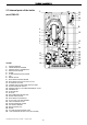
TECHNICAL CHARACTERISTICS 2.3 Internal parts of the boiler 5 26 27 28 11 mod. RKA 25 6 4 2 18 1 3 8 7 10 9 24 25 19 21 20 22 17 16 23 11 12 13 LEGEND 1. 2. 3. 4. 5. 6. 7. 8. 9. 10. 11. 12. 13. 14. 15. 16. 17. 18. 19. 20. 21. 22. 23. 24. 25. 26. 27. 28.
TECHNICAL CHARACTERISTICS 2.4 Water circuit LEGEND 1. 2. 3. 4. 5. 6. 7. 8. 9. 10. 11. 12. 13. 14. 15. 16. 17. 18. 19. 20. 21. 22. 23. 24. 25. 26. 27. 28. 29. 30. 31. 32. 33. 34. 35.
TECHNICAL CHARACTERISTICS Head (kPa) 2.5 Circulation pump head/flow graph 70 60 50 40 30 III 20 10 0 0 200 400 600 800 1000 1200 1400 1600 Flow l/h III Head available for the system at maximum speed Head available for the system with bypass 50% open Appliance Loss CONDENSING BOILOES WITH STORAGE - TG05A095.
TECHNICAL CHARACTERISTICS 2.6 DIAGNOCODE® series SM 20015 Printed Circuit Board Technical characteristics Part Number 76655LA M9 M10 M11 M8 M12 M13 M7 M6 M5 M4 M3 M2 M1 The new circuit boards greatly simplify the adjustment of the operating parameters of the entire system.
INSTALLATION INSTRUCTIONS 2.7 Control panel LEGEND 1. ON/OFF SWITCH 2. HEATING TEMPERATURE CONTROL KNOB 3. D.H.W TEMPERATURE CONTROL KNOB (only for model RKR 25). 4. OUTSIDE TEMPERATURE DISPLAY BUTTON (ONLY WITH OPTIONAL OUTDOOR SENSOR FITTED) 5. SERVICE BUTTON. 6. SUMMER, WINTER OR SUMMER/WINTER SELECTION BUTTON. 7. TERMINAL BOARD FOR EXTERNAL WIRING. 8. D.H.
INSTALLATION INSTRUCTIONS 3. INSTALLING THE APPLIANCE 3.1 Reference standard The following list is the full lists of codes of practice and British Standards That engineers should work to in the UK. It is law in the UK that a competent person installs all gas-burning appliances. Please ensure that the installer is a class of person approved for the time being by the Heath and Safety Executive for the purpose of carrying out this work. An approved engineer should be registered to an approved scheme i.e.
INSTALLATION INSTRUCTIONS 3.2 Unpacking ■ The materials (cardboard) used for packing the appliance are fully recyclable. ■ It is recommended that the packing material is only removed prior to installing the boiler. The manufacturer will not be held responsible for damage caused by incorrect storage of the product. ■ Packing materials (plastic bags, polystyrene, nails, etc.) must not be left within reach of children, in that these items represent a potential hazard. A.
INSTALLATION INSTRUCTIONS 3.3 Installing the boiler ■ The appliance must be installed exclusively on a flat vertical wall capable of supporting its weight. ■ When mounting the boiler on the wall, make absolutely sure that the boiler is fitted perfectly level. If the boiler is not level, the condensate will not flow correctly through the drainpipe but will instead accumulate inside the main exchanger and stop it from working. CONDENSING BOILOES WITH STORAGE - TG05A095.
INSTALLATION INSTRUCTIONS 3.4 Water connections In order to safeguard the heat exchanger and circulation pump, it is recommended that the system is hotflushed to remove any impurities (especially oil and grease) from the pipes and radiators. HR HWO G CWI HF 84.5 78 70 80 102 75.5 Please ensure that all discharge and safety pipes are connected and terminated in line with page 17 of this manual Make sure that the domestic water and central heating pipes are not used to earth the electrical system.
INSTALLATION INSTRUCTIONS 3.5 Central heating circuit The boiler is designed for use in a sealed central heating system in accordance with the requirements of BS 5449 and BS 6798. The system should be designed to operate with flow temperatures of up to 82°C. When designing the system, the pump head, expansion vessel size, mean radiator temperature, etc. must all be taken into account. Refer to the pump performance table for guidelines.
INSTALLATION INSTRUCTIONS 3.6 Condensate drain Termination to an internal soil and vent pipe Boiler FAILURE TO INSTALL THE CONDENSATE DISCHARGE PIPEWORK CORRECTLY WILL AFFECT THE RELIABLE OPERATION OF THE BOILER The condensate discharge pipe MUST NOT RISE at any point along its length. There MUST be a fall of AT LEAST 2.5° (50mm per metre) along the entire run. 50m m per m e tre of p 2.5° Min ipe run imum fa ll 450mm min I.
INSTALLATION INSTRUCTIONS 3.7 Discharge piping The discharge pipework from the tundish: 1. Shall fall continuously through its length. 2. Shall be of metal construction 3. Shall not be fitted with any valves or taps. 4. Shall discharge to a safe visible position, e.g. onto the surface of an external wall or into a gulley. 5. Shall have a minimum of 300 mm straight pipework directly from the tundish.
INSTALLATION INSTRUCTIONS 3.8 D.H.W. circulating loop C A a. unscrew cap A on the top of cylinder. b. Insert the copper pipe B, supplied by the manufacturer, into the ½” connection and than connect the loop pipe C. c. if the system requires an additional expansion vessel for the B D.H.W. circuit, insert a ‘T’ between the loop pipe and the ½” connection. Fig. 1 D.H.W. OUT LOOP PUMP TAPS TAPS TAPS COLD WATER MAINS HOT WATER FLOW TO TAPS CONDENSING BOILOES WITH STORAGE - TG05A095.
INSTALLATION INSTRUCTIONS 3.9 Gas connection The connection to the gas supply must be carried out by professionally qualified personnel, registered in accordance with current legislation and CORGI. When connecting the boiler to the gas supply pipe, only use appropriate gas fittings in accordance with the Gas Safety and Use Regulations..
INSTALLATION INSTRUCTIONS Electric power supply Connect the power supply to the terminal board inside the control panel as follows: • N Connect the earth wire (normally coloured green/yellow) to the terminal marked with the earth symbol “ “. A B neutral L • Ta Ta Se Se a. Switch off the power supply at the main switch. b. Remove the front panel of the boiler. c. Slacken the screws and remove plate A (see fig. 1). d.
INSTALLATION INSTRUCTIONS 3.12 Connecting the “Remoto” thermostat/timer If the optional remote thermostat/timer has been purchased, this must be connected to the modulation board installed in the boiler control panel. To access the modulation board, proceed as follows: 1. Switch off the power supply at the main switch. 2. Remove the front panel of the boiler. 3. Bend the two panel support brackets outwards slightly and at the same time rotate the panel downwards. 4.
INSTALLATION INSTRUCTIONS 6. Connect plug M1 to the interface board and plug M11 to the modulation board (fig. 1). RL1 7 8 M3 M1 A M11 Interfaccia 6 M8 M2 M9 M10 B 7 Connect the grey and orange wires to plug M2 of the interface board and to the terminal board. 8. Connect the wires of plug M3 on the interface board to the terminal board. M12 M13 9. Remove jumper TA-TA and set the boiler to SUMMER mode. M7 10. Connect the remote control to the terminal board using a 2 x 0.
INSTALLATION INSTRUCTIONS Regulating the Flow temperature in accordance with the outdoor temperature The outdoor sensor can be connected either to the remote control or directly to circuit board SM 20015. The sensor can thus be managed in one of two ways: • if the sensor is wired to the remote control, the climatic compensation curve is set by the remote itself (see remote control installation and operating manual).
INSTALLATION INSTRUCTIONS 3.13 Flue connections In order to ensure that the appliance functions correctly and efficiently, the flue connection between the boiler and the flue terminal must be made using original components specifically designed for condensing boilers. Traditional flue components cannot be used for conveying exhaust fumes from condensing boilers, nor vice versa.
INSTALLATION INSTRUCTIONS Flue position IMPORTANT: THE FLUE SYSTEM SHALL BE INSTALLED IN ACCORDANCE WITH THE RECOMMENDATIONS CONTAINED IN BS 5440:1. The boiler MUST be installed so that the terminal is exposed to the external air. It is important that the position of the terminal allows free passage of air across it at all times. If the terminal discharges into a pathway or passageway check that combustion products will not cause nuisance and that the terminal will not obstruct the passageway.
INSTALLATION INSTRUCTIONS Chimneys – UNI 7129/01 distance ≤5m 5. 60° pitched roof If the ridge of the roof is further than 1.20 m from the chimney, the chimney must be at least 2.6 m higher than the edge of the roof. 0.50 m 0.50 m above the ridge distance > 1.30 m 3 distance 0.80 m ≤ 1.30 m backflow zone 0.50 m above the ridge 30° distance > 1.50 m distance ≤ 1.50 m 4 backflow zone 45° distance > 1.20 m distance ≤ 1.20 m 5 backflow zone 60° If the ridge of the roof is 1.
INSTALLATION INSTRUCTIONS Flue type - kit K Horizontal coaxial flue system Ø 100/60 in PPS polypropylene adjustable through 360°. Discharges exhaust fumes and draws air from atmosphere. Suitable for condensing boilers only. Discharges exhaust gases and draws combustion air by means of two coaxial ducts. The external Ø100 duct draws the combustion air while the Ø60 plastic inner duct discharges the exhaust fumes.
INSTALLATION INSTRUCTIONS ■ Flue type - kit H Separate air intake/exhaust fumes discharge system in PPS polypropylene adjustable through 360°. The dual pipe system discharges exhaust fumes into a chimney and draws air from atmosphere. Suitable for condensing boilers only. Discharges exhaust gases and draws combustion air through two separate Ø 80 ducts. MAXIMUM FLUE LENGTH: Ø 80/80: 50 m.
INSTALLATION INSTRUCTIONS Flue type - kit V Vertical coaxial flue system in PPS polypropylene. Discharges exhaust fumes and draws air directly from high Level. Suitable condensing boilers Suitable forforcondensing boilers only. only. Discharges exhaust gases and draws Discharges draws comburent airexhaust at roof gases level byand means of combustion air at roof level by means two coaxial ducts. The external Ø 100 duct of two coaxial ducts.
INSTALLATION INSTRUCTIONS 4. INITIAL START-UP 4.1 General warnings The following operations must be carried out by professionally qualified personnel, registered in accordance with current legislation and authorised by Radiant Bruciatori S.p.A. The boiler leaves the factory pre-set and tested for burning either Natural Gas or LPG. Nevertheless, when starting the boiler for the first time, make sure that the information on the rating plate corresponds to the type of gas being supplied to the boiler.
INSTALLATION INSTRUCTIONS 4.2 Filling the system Use only a WRAS approved filling loop for connection and filling of the primary system. This should be disconnected when not in use. AIR VENT VALVE PLUG AIR VENT VALVE Check the properties of the water supply and install the appropriate treatment devices if the mains water has a hardness rating more than 25 °F in order to prevent scaling and eventual damage to the D.H.W heat exchanger.
INSTALLATION INSTRUCTIONS 4.3 Flushing the system TO FLUSH OUT THE PRIMARY SIDE OF THIS UNIT. 1. 2. 3. 4. 5. 6. Fill the boiler as per the filling instructions. Using a drain off cock on the lowest point of the system allow the water to drain from the system and boiler. In order to flush the system correctly turn off all radiators open the filling loop and drain cock simultaneously and allow the water to flow through the boiler.
INSTALLATION INSTRUCTIONS 4.5 Starting up the boiler Once the system has been filled, proceed as follows: • Check that the exhaust flue is free of obstructions and correctly connected to the boiler. Table n°1 Gas type G20 G 30 G 31 CO2 % 9.4 10.9 10.96 • Switch on the power supply to the boiler. • Open the gas isolation valve. • Place switch 1 in the ON position (see 2.7 “Control Panel”), after a few seconds the circulation pump will start to run.
REGULATION INSTRUCTIONS 5. COMMISSIONING THE BOILER 5.1 Parameter table PARAMETER N° FUNCTION PARAMETER VALUE OPTIONS 1 SELECTS TYPE OF BOILER 00 01 02 INSTANTANEOUS BOILER BOILER WITH STORAGE TANK BOILER TANK WITH +7°(stored water temp. increased by 7°) 2 SELECTS TYPE OF GAS 00 01 NATURAL GAS LPG 3 SETS THE CENTRAL HEATING TEMPERATURE 00 01 30-80°C FOR STANDARD SYSTEMS 25-40°C FOR FLOOR SYSTEMS 4 SELECTS THE PUMP MODE DURING HEATING PHASE 00 01 .
REGULATION INSTRUCTIONS 5.2 Parameters programming 5.2.1 Entering Parameters Menu Each time you wish to change or check any parameter value, you should access the parameter menu, following this procedure: 1. Place the ON/OFF switch in OFF position; 2. Keep pressed the (▲) and (▼) buttons, switch on the boiler and wait for the display to show ‘PL’ – ‘0’; Release (▲) and (▼) buttons; S PL 3.
REGULATION INSTRUCTIONS 5.2.2 Parameters settings To enter the parameters menu, follow the procedure shown at page n° 35 (steps 1-6). 02 ◄ PARAMETER N° 1 – TYPE OF BOILER 7. Use (▲) and (▼) buttons to modify the value of the parameter: 00 = Instantaneous boiler; 01 = Storage boiler; 02 = ‘Storage comfort’ boiler. With this option you’ll have stored water with 7° higher temperature; S 1 S 01 8. Press and release the service (S) button to confirm your choice.
REGULATION INSTRUCTIONS 00 ◄ PARAMETER N° 4 – PUMP MODE ON CENTRAL HEATING PHASE 7. Use (▲) and (▼) buttons to modify the value of the parameter: 00 = STANDARD (3 ‘ OVERRUN) 01 = ALWAYS RUNNING (to be activated ONLY FOR SYSTEM BOILERS); S 8. Press and release the service (S) button to confirm your choice. Number 4 will appear on the display; 9. If you have to modify some other parameter, follow the 4 – 5 steps (p.
REGULATION INSTRUCTIONS 36 ◄ PARAMETER N° 7 – CENTRAL HEATING PUMP OVERRUN 7. Use (▲) and (▼) buttons to modify the value of the parameter: 00 = 0 99 = 99 x 5’’ = 450 ‘’ = 7.5’ Default value is set to 36 = 180’’ = 3’ S 7 8. Press and release the service (S) button to confirm your choice. Number 7 will appear on the display; 9. If you have to modify some other parameter, follow the 4 – 5 steps (p.
REGULATION INSTRUCTIONS 24 ◄ PARAMETER N° 10 – MINIMUM HEATING POWER 7. The value of the parameter must be equal to the one shown into page 35 table. Use (▲) and (▼) buttons to modify the value of the parameter: S 24 for Natural Gas 21 for L.P.G. 10 S 8. Press and release the service (S) button to confirm your choice. Number 10 will appear on the display; 9. If you have to modify some other parameter, follow the 4 – 5 steps (p.
REGULATION INSTRUCTIONS 5.3 Gas data 5.3.1 Data Tables Table n°1 – CO2 values CO2 % Gas type G20 Natural Gas 9.4 G 30 Butane 10.9 G 31 Propane 10.96 NATURAL GAS G20 Table n°2 - Gas data table Lower Wobbe index (15°C; 1013 mbar) LIQUID BUTANE GAS G30 LIQUID PROPANE GAS G31 MJ/Nm3 45.67 80.58 70.69 mbar 20 30 37 3 m /h 2.64 - - kg/h - 1.94 1.94 cfh 93.22 36.63 36.63 Nominal supply pressure Consumption (15°C; 1013 mbar) 5.3.
REGULATION INSTRUCTIONS 5.4 Regulating the stepped ignition sequence B M4 M8 M10 M12 M2 M4 M1 M9 Each time the appliance is started up, in order to provide optimum ignition and an even flame distribution over the entire surface of the burner, a stepped ignition sequence is used. This consists of an instantaneous and brief increase in the gas pressure during the ignition phase only. CM1 M7 M11 M6 A M5 M3 M13 P2 MIN The correct setting for the appliance can be checked as follows (fig.
REGULATION INSTRUCTIONS 5.5 Converting the boiler for different gas type M10 M12 M2 M4 M1 M9 The conversion of a boiler from burning natural gas to LPG, or vice versa, must be carried out exclusively by professionally qualified personnel, registered in accordance with current legislation. B M4 M8 Check that the gas supply pipe is suitable for the new fuel type.
USER INSTRUCTIONS 6. SERVICING THE BOILER 6.1 General warnings All maintenance operations must be carried out according to UNI-CIG 7129/01, and subsequent updates, by professionally qualified personnel, registered in accordance with current legislation. All warranty work is to be carried out and authorised by Radiant Bruciatori S.p.A Service centre.
USER INSTRUCTIONS 6.3 Maintenance for unvented components It is essential that the unvented hot water components have a regular maintenance programme. It is Radiant’s recommendation that this be carried out in conjunction with the annual boiler service. The STORAGE CYLINDER and CENTRAL HEATING PRESSURE RELIEF VALVES should be manually operated for a period of not less than 5 seconds each to: i. ii. Check the flow of water through the valve and the final discharge route to the drain.
USER INSTRUCTIONS 6.4 Accessing the boiler All maintenance operations require one or more of the boiler casing panels to be removed. The side panels can only be removed after the front panel has been removed. Front panel: Remove the fixing screws at the lower edge of the front panel. Grasp the lower part of the panel and pull it outwards (fig. 1) and then up . Left and right side panel: Remove the fixing screws at the front and lower edge of the side panel to remove.
USER INSTRUCTIONS 6.5 Draining the central heating and the domestic hot water systems DRAINING THE CENTRAL HEATING SYSTEM If the need arises to drain the system, this can be done as follows: • Switch the system to “WINTER” mode and ignite the boiler. • Switch off the power supply to the boiler. • Wait for the boiler to cool down. • Connect a hosepipe to the system drain point and locate the other end of the hose in a suitable drainage system. • Open the system drain valve (fig. 1).
S 20 21 22 R C VD M5 M4 M6 M5 5 M3 SR 6 7 8 black MF 9 M2 48 49 50 light-blue 45 46 47 red SS white M13 black P light-blue 18 19 brown light-blue M9 M12 1.
USER INSTRUCTIONS 6.7 Troubleshooting ERROR CODE POSSIBLE CAUSE PROBLEM NO FLAME WITH NO IGNITION a. NO GAS. b. IGNITION ELECTRODE BROKEN OR EARTHED. c. IGNITION CIRCUIT BOARD S4565QM MALFUNCTION. d. GAS VALVE MALFUNCTION. e. MECHANICAL MINIMUM ADJUSTMENT (ON GAS VALVE). TOO LOW OR SLOW IGNITION ADJUSTMENT TOO LOW. f. VALVE INLET PRESSURE TOO HIGH (FOR LPG BOILERS ONLY). 01 REMEDY a. b. c. d. e. f. CHECK MAINS SUPPLY. REPLACE PART. REPLACE PART. REPLACE PART. REGULATE MINIMUM OR SLOW IGNITION.
USER INSTRUCTIONS 6.8 Diagnostics ■ Error codes: 1 IONISATION BLOCK 2 SAFETY THERMOSTAT TRIPPED 4 WATER PRESSURE ALARM 5 HEATING SENSOR MALFUNCTION 6 D.H.W. SENSOR MALFUNCTION 14 GENERAL ALARM (AIR PRESSURE SWITCH OR WATER PRESSURE SWITCH) 22 PARAMETER PROGRAMMING REQUEST ■ Signal codes SIGNAL CODE 7 8 9 31 SIGNAL TYPE DESCRIPTION CHIMNEY-SWEEP FUNCTION ACTIVE PRESSING THE “SERVICE” BUTTON FOR 5 SECONDS ACTIVATES THE CHIMNEY-SWEEP FUNCTION.
USER INSTRUCTIONS 6.9 Parts list ■ main components PART NUMBER DESCRIPTION 20025LA ANODE W/ CONTROL VALVE 9 20040LA PLATE EXCHANGER 16 P 9 20050LA CONDENSING EXCHANGER RKA R 4+1 GM30-75-064 9 20051LA CYLINDER 14 LT. RKA 9 24029LA CIRCULATING PUMP MOTOR RSL 15/6-3-KUCLF6 9 24046LA CIRCULATING PUMP RSL 15/6-3-KUCLF6 W/C1 9 27044LA SIPHON RK25 9 35021LA IGNITION ELECTRODE FOR RK GM10-35-025 9 35022LA FLAME IONISATION ELECTRODE FOR RK GM10-35-026 9 36067LA ELECTR.
USER INSTRUCTIONS ■ MULTIPLEX unit – mod.
RADIANT BRUCIATORI s.p.a. Via Pantanelli, 164/166 - 61025 Loc. Montelabbate (PU) Tel. +39 0721 9079.1 • fax. +39 0721 9079279 e-mail: tecnico@radiant • Internet: http://www.radiant.it RADIANT HELPLINE UK Technical Helpline Spares Email - 0870 770 0414 - 0870 770 0425 - info@portsdean.co.uk THE TECHNICAL DATA AND MEASUREMENTS ARE PROVIDED FOR INFORMATION PURPOSES ONLY AND ARE NOT BINDING. THE COMPANY RESERVES THE RIGHT TO APPLY VARIATIONS WITHOUT PRIOR NOTIFICATION.