
Instructions / Assembly

ASSEMBLY INSTRUCTIONS (CONT.)
8
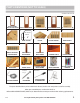
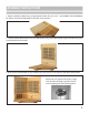
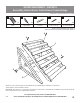
10. Feed the main power cable through hole in ROOF and plug securely into receptacle on back of POWER
SUPPLY box. Secure the ROOF COVER with 3/4” SCREWS.
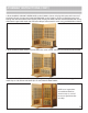
11. Connect touch screen control panel as shown and mount frame to BACK PANEL with 2” SCREWS.
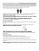
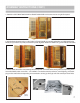
12. Attach the DOOR HANDLE to the GLASS DOOR by assembling parts (A) as shown (for top and bottom of handle,
note position of glass door between parts), then inserting set screws (B) into handle and screwing into tting (C).
GLASS
DOOR
OUTSIDEINSIDE
A
B
C
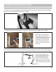
NOTE: Outside handle will look
like this on top and bottom, once
assembled through glass holes,
before attaching inside handle
using set screws. You may need to
adjust ttings (C) so they line up with
set screw holes before inserting screws.
NOTE: Please see info on Page 11
about USB cable usage. This is the
extra black wire, with USB connection
on end, coming out of back of the
Control Panel. This is NOT used to
connect Control Panel and, if not
using, can be tucked behind panel
out of way.