
User Manual

COMPONENTS
1 4
2 5
3
Body
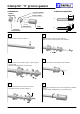
STRIPPING DIMENSIONS
Strip the cable as shown in sketch 1.
Slide the back nut, the washer and the ‘V’ groove gasket
onto the cable.
Slide the clamp braid sleeve over the braid.
Solder the centre contact onto the inner conductor.
Screw sub-assembly into the connector body with the adapted
wrench.
Recommended coupling torque ( see connector TDS ).
6
Clamp 02 : ‘V’ groove gasket
Fold the braid back and trim off the extra braid.
Trim dielectric back as shown in sketch 2.
Slide the back nut over the cable assembly.
Slide the centre contact onto the inner conductor.
‘V’ groove gasket
Back nut
b
Centre contact
Clamp braid
1
2
1
2
1
2
Washer
1
1
1
1
a
e
2
RF interconnect solutions